Igbts, Sigma-delta modulator adcs – Altera Multiaxis Motor Control Board User Manual
Page 8
Page 8
Functional Description
Multiaxis Motor Control Board
February 2014
Altera Corporation
The time constant of the AC coupling allows the brake resistor to be active for no
more than 1 ms if the HSMC_MOTOR_BRAKE signal remains asserted.
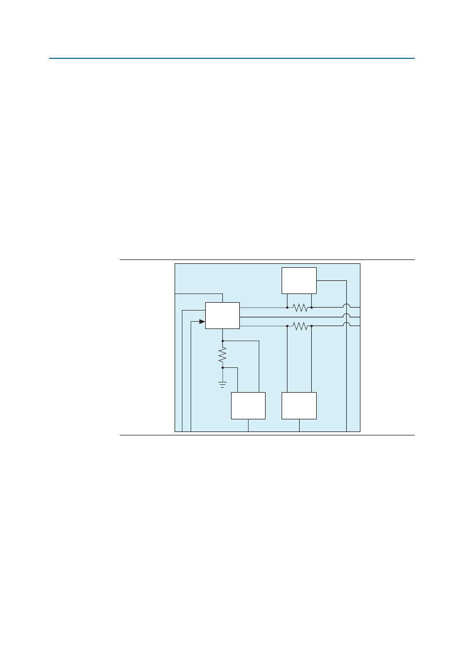
IGBTs
The Multiaxis Motor Control Board uses Fairchild FNB41560/B2 600V/15A smart
power modules for each of the four motor channels (
Figure 5
). These modules are
three-phase IGBT inverter bridges including control ICs for gate driving and
protection.
Murata MEE1S2415SC isolated DC/DC converters generate floating bootstrap
supplies for the gate drivers from the 15V supply. The bootstrap voltages also power
the ADCs that sample the motor current, via simple zener diode regulators.
The Multiaxis Motor Control Board uses software to ensure that the low side IGBT
activates long enough to produce the correct bootstrap voltage (refer to the Fairchild
AN-9070 Smart Power Module Motion-SPM Products Application Note). The bootstrap
capacitor for each channel on the Multiaxis Motor Control Board is 22 F.
Sigma-Delta Modulator ADCs
The Multiaxis Motor Control Board includes multiple Analog Devices AD7401
differential input sigma-delta modulators, each clocked at 20 MHz to monitor and
measure key voltage, current, and resolver output quantities. The Multiaxis Motor
Control Board uses isolated ADCs except the resolver encoder feedback conversion.
The Multiaxis Motor Control Board demodulates the bit streams from the ADCs in the
FPGA on the host board. The Multiaxis Motor Control Board isolates the digital
encoded data at the HSMC connector.
Figure 5. IGBTs
Isolated
SD-ADC
20 MSPS
3.3 V
3-Phase
IGBT Inverter
500 W
Isolated
SD-ADC
20 MSPS
Isolated
SD-ADC
20 MSPS