Digital i/o isolators, Power supplies – Altera Multiaxis Motor Control Board User Manual
Page 5
Functional Description
Page 5
Multiaxis Motor Control Board
February 2014
Altera Corporation
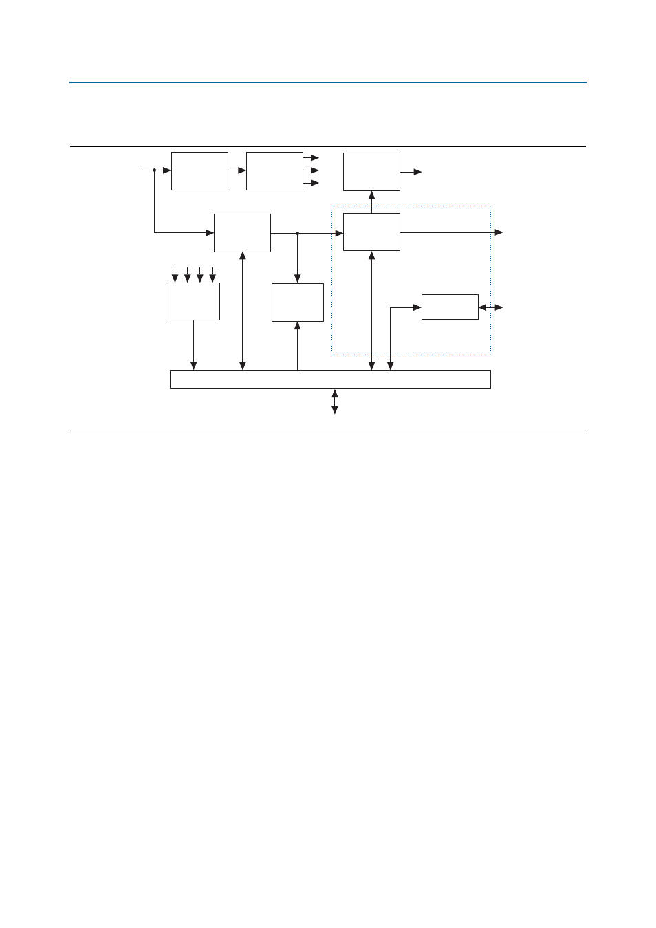
Figure 2
shows a high-level block diagram of the Multiaxis Motor Control Board.
The following sections describe the functional blocks.
Digital I/O Isolators
Analog Devices ADuM1401 digital isolators isolate all digital I/O signals on the
Multiaxis Motor Control Board. They provide complete electrical isolation between
the host FPGA board and the power electronics on the Multiaxis Motor Control
Board. In some circuit locations, the board uses Silicon Labs Si8440 or Si8441 digital
isolators for their output behavior during power down, to prevent transient control
signals on the IGBT drivers.
One side of each isolator connects to the HSMC connector and takes power from the
HSMC connector. The other side of each isolator takes power from an isolated power
supply on the Multiaxis Motor Control Board.
Power Supplies
The Multiaxis Motor Control Board converts mains input to the DC link and a number
of lower voltages for logic and interfacing.
Figure 2. Block Diagram
Isolated
22-V Supply
Low-Voltage
Logic Supplies
400-V
DC Link
Bootstrap
Circuit
IGBTs
x4 Channel
Encoder
Interface
Current and
Voltage
Sensing
Ballast/
Brake
Mains
Input
Digital I/O Isolators
HSMC
Motors
Encoders