Connecting the motors – Altera Multiaxis Motor Control Board User Manual
Page 3
Setting Up the Multiaxis Motor Control Board
Page 3
Multiaxis Motor Control Board
February 2014
Altera Corporation
4. Connect the encoder cable to the screw terminal on the relevant terminal block for
channel you intend to use (
Table 2
).
Connecting the Motors
To prevent electrical shocks before connecting or disconnecting the motor:
1. Always shut down the motor control application on the host board.
2. Disconnect the Multiaxis Motor Control Board from the mains supply.
3. Ensure the DC link capacitors are discharged.
4. Use the four-way screw terminal block to connect each motor.
Table 3
lists motor
connectors.
5. Connect the motor to the screw terminal connector for the channel you intend to
use (
Table 6
).
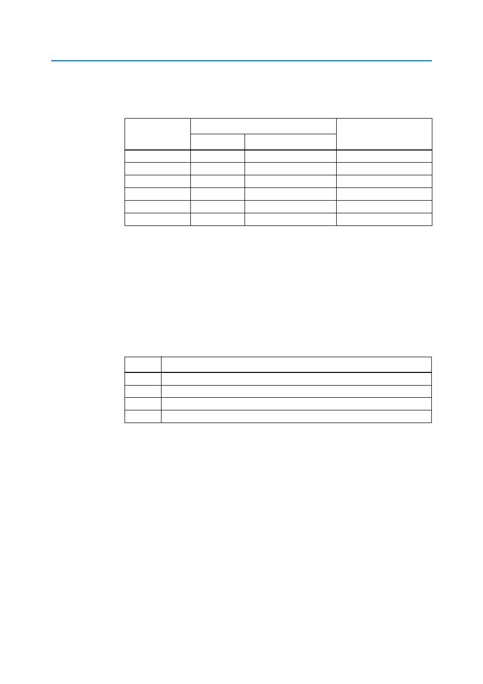
Table 2. Screw Terminal Connections for BiSS and EnDat Encoders
Signal Name
Cable Color
Screw Terminal
(J9, J23, J37, J51)
BiSS
EnDat
Data+
PInk
Grey
18
Data-
Grey
Pink
19
Clock+
Yellow
Violet
14
Clock-
Green
Yellow
15
Power
White
Blue and brown/green
1
Ground
Brown
White and white/green
20
Table 3. Motor Connectors
Channel
Motor Connector
0
J2
1
J16
2
J30
3
J44