Reset distribution, Starting configuration, Factory & user configurations – Altera Nios Development Board Cyclone II Edition User Manual
Page 48: R to, Figure 2–17
2–36
Reference Manual
Altera Corporation
Nios Development Board Cyclone II Edition
May 2007
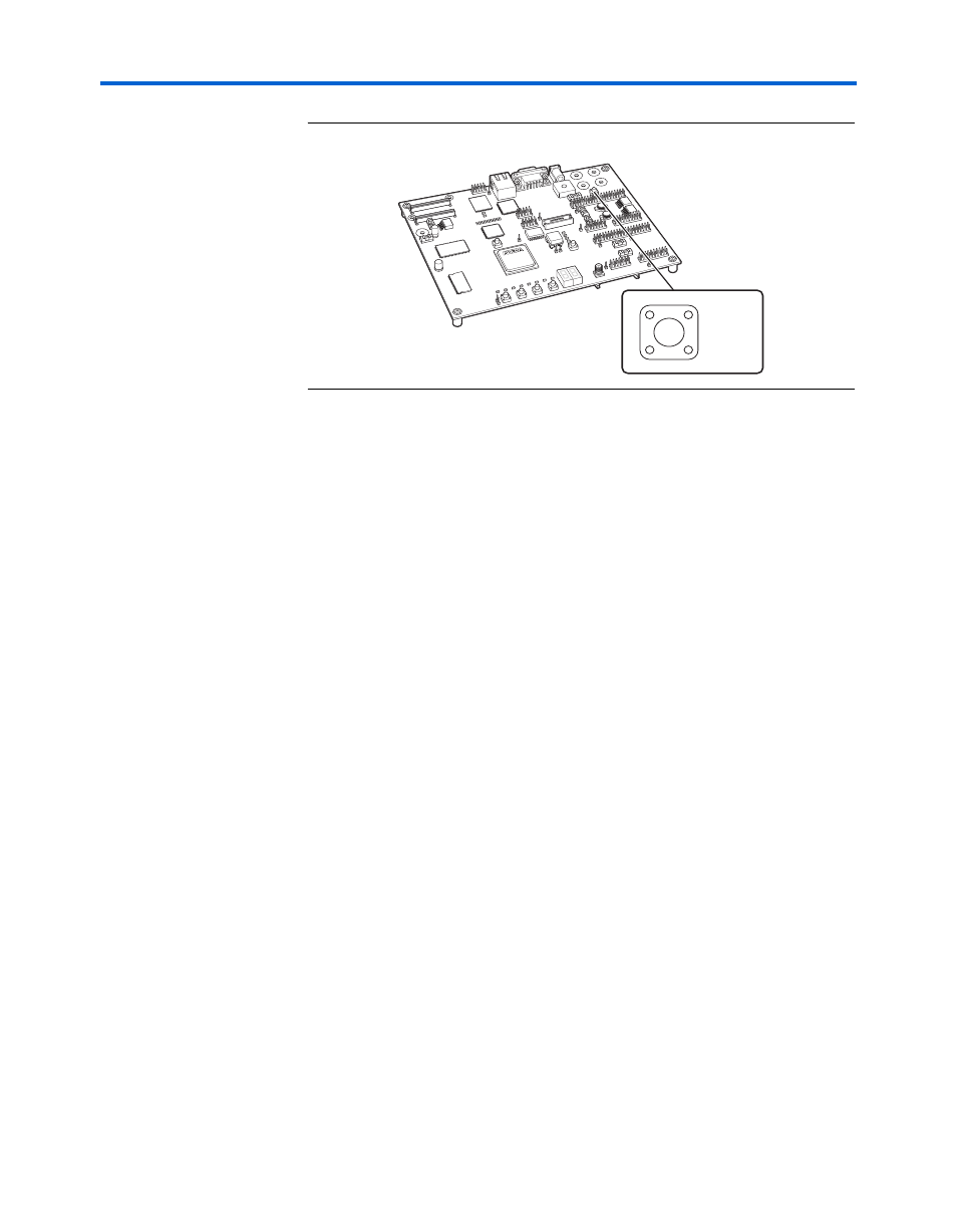
Board Components
Figure 2–17. Reset, Config Button
Reset Distribution
The EPM7256AE device takes a power-on reset pulse from the Linear
Technologies 1326 power-sense/reset-generator chip (U18) and
distributes it (through internal logic) to other reset pins on the board, that
include the following:
■
LAN91C111 (Ethernet MAC/PHY) reset
■
Flash memory reset
■
CompactFlash reset
■
Reset signals delivered to the expansion prototype connectors
(PROTO1 & PROTO2)
Starting Configuration
The following four methods start a configuration sequence:
1.
Board power-on
2.
Pressing the Reset, Config button (SW10).
3.
Asserting (driving 0 volts on) the
pld_reconfigreq_n input pin
of the EPM7256AE device (U3 pin 94) from the FPGA (U62 pin
AA14).
4.
Pressing the Factory Config button (SW9).
Factory & User Configurations
The configuration controller can manage two separate FPGA
configurations stored in flash memory U5. These two configurations are
referred to as the factory configuration and the user configuration. A
Reset,
Config
SW10