Mictor connector (j20) – Altera Stratix II EP2S180 DSP Development Board User Manual
Page 44
2–36
Core Version a.b.c variable
Altera Corporation
Stratix II EP2S180 DSP Development Board Reference Manual
Board Components
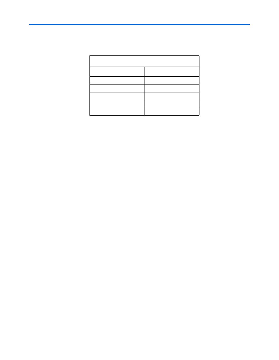
lists the reference information for the CompactFlash
connector.
f
For general information on CompactFlash, see www.compactflash.org.
Mictor Connector (J20)
The Mictor connector (J20) can be used to transmit up to 27 high-speed
I/O signals with very low noise via a shielded Mictor cable. J20 is used as
a debug port. Twenty-five of the Mictor connector signals are used as
data, and two signals are used as clock input and clock output.
Most pins on J20 connect to I/O pins on the Stratix II device (U18). For
systems that do not use the Mictor connector for debugging the Nios II
processor, any on-chip signals can be routed to I/O pins and probed at
J20 via a Mictor cable. External scopes and logic analyzers can connect to
J20 and analyze a large number of signals simultaneously.
f
For details on Nios II debugging products that use the Mictor connector,
see www.altera.com.
shows an example of an in-target system analyzer ISA-Nios/T
(sold separately) by First Silicon Solutions (FS2) Inc. connected to the
Mictor connector. For details see www.fs2.com.
Table 2–29. CompactFlash Connector Reference
Item
Description
Board reference
CON1
Part Number
53856-5010
Device description
CompactFlash connector
Manufacturer
Molex
Manufacturer web site
www.molex.com