Altera Stratix II EP2S180 DSP Development Board User Manual
Page 45
Altera Corporation
Core Version a.b.c variable
2–37
Stratix II EP2S180 DSP Development Board Reference Manual
Board Components & Interfaces
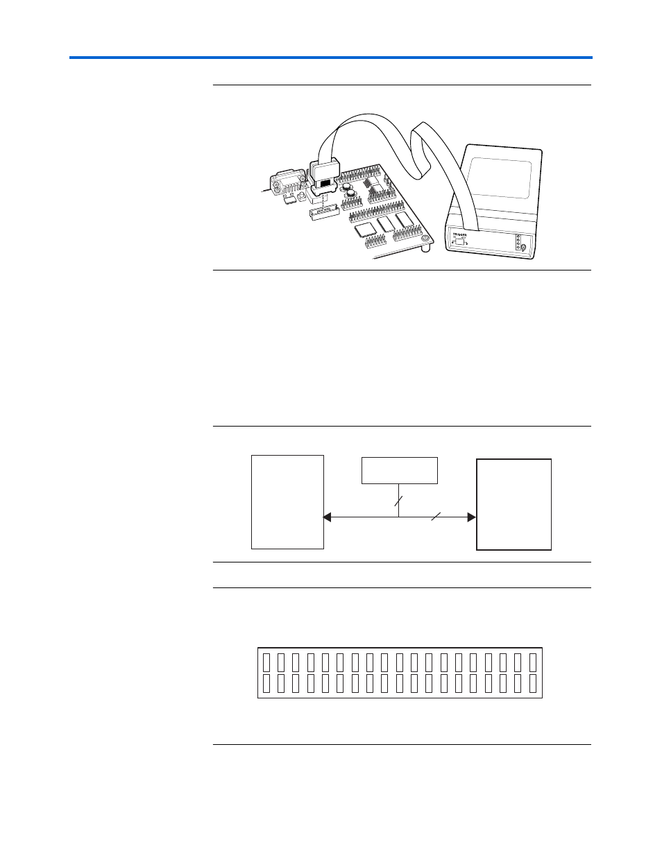
Figure 2–6. An ISA-Nios/T Connecting to the Mictor Connector (J20)
Five
of the signals connect to both the JTAG pins on the Stratix II device
(U18) and the Stratix II device’s JTAG connector (J24). The JTAG signals
have special usage requirements. You cannot use J20 and J24 at the same
time.
below shows connections from the Mictor connector to the
Stratix II device.
shows the pin-out for J20. Unless otherwise
noted, labels indicate Stratix II device pin numbers.
Figure 2–7. Mictor Connector Signaling
Figure 2–8. Debug Mictor Connector - J20
BUSY
COMM
RUN
POWER
1
J25
(J20)
(U18)
Stratix II Device
40
JTAG Connector
(J21)
5
Mictor Connector
38 T23
37 P27
36 T22
35 P26
34 T28
33 P29
32 T27
31 P28
30 R29
29 N27
28 R28
27 N26
26 R25
25 N25
24 R24
23 N24
22 R23
21 TRST
20 R22
19 TDI
18 R27
17 TMS
16 R26
15 TCK
14 VCC3.3
13 M27
12 VCC3.3
11 TDO
10 P25
9 M26
8 P24
7 N23
6 TR_CLK
5 N22
4 NC
3 NC
2 NC
1 NC