Signal definitions, Interface diagrams – Altera SerialLite II Protocol User Manual
Page 13
Altera Corporation
13
SerialLite II Protocol Reference Manual
SerialLite II Specification
Signal Definitions
provides a list of the interface signals, including a short
description of their functionality.
Interface Diagrams
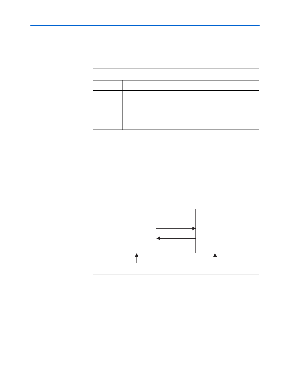
The SerialLite II protocol supports an interface that recovers the clock and
data for a serial bit.
shows the SerialLite II protocol in asynchronous mode, where
the clock and data is recovered from the serial bit stream, and each device
has its own reference clock.
Figure 2–4. Asynchronous Clock & Data Recovery
shows the SerialLite II protocol in synchronous
mode, where the clock and data is recovered from the serial bit stream,
and the reference clock is shared between devices.
Table 2–1. Interface Signals
Signal
Direction
Description
TD[0-N]
Output
Transmit data—Carries payload data and in-band
control words. TD connects to RD of the receiving
device.
RD[0-N]
Input
Receive data—Carries payload and in-band control
words. RD connects to TD of the transmitting
device.
Device A
Device B
TD[0-N]
RD[0-N]
RD[0-N]
TD[0-N]
REFCLK
REFCLK