System ir, Emitter, Receiver – Atlona AT UHD CLSO 612 V2 User Manual
Page 21: White : - red :+ red: pwr white : ir black, Pwr ir
21
atlona.com
Toll free: 1-877-536-3976
Local: 1-408-962-0515
IR
DC 24V
FW
LAN
1
2
3
4
INPUT
OUTPUT
IR IN
PWRIR
- +
IR OUT
5
6
IR IN
PWRIR
- +
IR OUT
IR IN
MIC/LINE IN
48V
MIC
LINE
PWRIR
- +
IR OUT
IR IN
PWRIR
- +
IR OUT
-
+
-
+
-
+
IR IN
L
R
-
+
-
+
L
R
-
+
-
+
L
R
PWRIR
- +
IR OUT
IR IN
PWRIR
- +
IR OUT
RS-232
RX TX
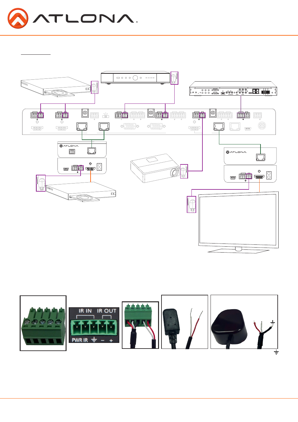
CLSO-612 has multiple IR routing options, allowing it to adapt to most IR needs.
System IR is typically used to connect to control system processors. The signal is routed through the
System IR IN and repeated to out all the IR OUT ports, including the HDBaseT ports. This input may
also be used to control the CLSO-612.
Note: HDBaseT ports must be connected to HDBaseT receivers and transmitters with IR capabilities.
Ex. AT-HDTX-IR, AT-HDTX-WP, AT-HDWP-IR, AT-HDRX-IR, etc
System IR
CAT5e/6/7 OUT
DC 24V
- +
AT-HDTX-IR
FIRMWARE
LINK
POWER
IR IN
HDMI IN
PWR IR
IR OUT
- +
NO
NC
COM
NO
NC
COM
NO
NC
COM
NO
NC
COM
GND
SIG
+12V
GND
SIG
+12V
GND
SIG
+12V
GND
SIG
+12V
1
2
3
4
RELAYS
WIFI 2
ZIGBEE
12V DC
IR OUT
ID
FACTORY
RESTORE
SERIAL 1
SERIAL 2
HDMI
COMPONENT
VIDEO OUT
ETHERNET
CONTACTS
AUDIO OUT
AUDIO IN
WIFI 1
eSATA
DIGITAL
COAX OUT
1
2
3
4
5
6
L
R
CAT5e/6/7 IN
AT-HDRX-IR
FIRMWARE
LINK
POWER
IR IN
HDMI OUT
PWR IR
IR OUT
- +
Control System Processor
White: - Red:+
Red: PWR White: IR Black:
IR
1
4
5
3
2
-
+
Emitter
PWR IR
Receiver
For your convenience the cables do not come pre-terminated. Each item, whether it’s an IR receiver or IR
emitter, will have wires exposed. Each wire is encased in a different colored cover. A female IR captive screw
connector has been included (see picture 1).
IR pin outs have been included for the included IR emitter and IR receiver (see picture 2 & 3). The wires are
colored for each pin (see picture 4 and 5).