Panel description, Front panel, Back panel – Atlona AT UHD CLSO 612 V2 User Manual
Page 4: Vga 5 and 6 - connect analog video sources here
4
atlona.com
Toll free: 1-877-536-3976
Local: 1-408-962-0515
DC 24V
FW
LAN
1
2
3
4
INPUT
OUTPUT
IR IN
PWRIR
- +
IR OUT
5
6
INPUT
AT-UHD-CLSO-612
FUNCTION
IR IN
PWRIR
- +
IR OUT
IR IN
MIC/LINE IN
48V
MIC
LINE
PWRIR
- +
IR OUT
IR IN
PWRIR
- +
IR OUT
-
+
-
+
-
+
IR IN
L
R
-
+
-
+
L
R
-
+
-
+
L
R
PWRIR
- +
IR OUT
IR IN
PWRIR
- +
IR OUT
5
6
<
<
<
>
4
1
2
3
MENU
ENTER
VOLUME
MUTE
POWER
RS-232
RX TX
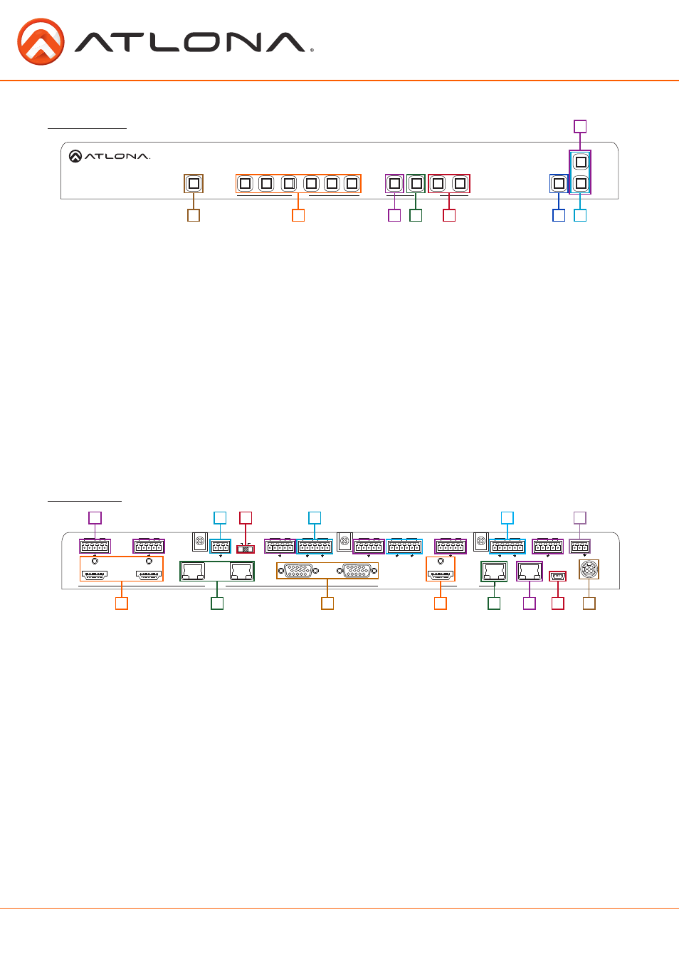
Panel Description
Front Panel
1. Power - Use to turn the unit on or place into standby. LED will illuminate blue for on and red for
standby
2. Input - Switch between inputs - current input is blue
1 - HDMI input 1 - Used while updating MCU firmware
2 - HDMI input 2 - Used while updating OSD firmware
3 - HDBaseT input 1 - Used while updating FPGA firmware
4 - HDBaseT input 2
5 - Multifunction analog input 1
6 - Multifunction analog input 2
3. Menu - Access the OSD menu - also used as a back button within the OSD
4. Enter - Select options within the OSD menu
5. < and > - Changes values of the currently select option (i.e contrast to 50)
6. Mute - Silences all audio output from the CLSO-612
7. Volume up/down - Adjusts output master volume
8.
^ and Use to navigate between selections within the OSD menu
1
1
3
6
7
8
4
2
3
2
9
10
11
12
13
14
5
4
5
6
7
8
Back Panel
1. HDMI 1 and 2 - Connect HDMI sources here
2. HDBaseT 3 and 4 - Connect HDBaseT transmitters here (ex. AT-HDTX-WP, AT-HDVS-TX-WP, etc)
Note: Power source equipment (PSE) transmitters require external power (ex. AT-HDTX, AT-HDTX-IR, etc)
3. VGA 5 and 6 - Connect analog video sources here
Note: Compatible with component, composite, and S-Video signals
4. HDMI Output - Connect to local display
5. HDBaseT Output - Connect to compatible HDBaseT displays or compatible receivers
(ex.
AT-HDRX-RSNET,
etc)
Note: Compatible PoCc receivers do not need power
6. LAN port - TCP/IP (Ethernet)
7. Firmware port - Connect to a PC with a USB cable for firmware updating
8. DC 24V port - Connect included power supply here
9. IR ports - IR control systems and compatible IR emitters connect to these ports (see pages 20-21)
10. MIC/LINE IN - Connect a microphone to this port
11. MIC Switch - Match microphone input to type of microphone in use
12. Audio In - Audio input ports for analog inputs 5 and 6
13. Audio Out - Audio output to audio amplifiers (ex. AT-PA100-G2) or audio systems
14. RS-232 port - Connect control system or PC here
DC 24V
FW
LAN
1
2
3
4
INPUT
OUTPUT
IR IN
PWRIR
- +
IR OUT
5
6
INPUT
AT-UHD-CLSO-612
FUNCTION
IR IN
PWRIR
- +
IR OUT
IR IN
MIC/LINE IN
48V
MIC
LINE
PWRIR
- +
IR OUT
IR IN
PWRIR
- +
IR OUT
-
+
-
+
-
+
IR IN
L
R
-
+
-
+
L
R
-
+
-
+
L
R
PWRIR
- +
IR OUT
IR IN
PWRIR
- +
IR OUT
5
6
<
<
<
>
4
1
2
3
MENU
ENTER
VOLUME
MUTE
POWER
RS-232
RX TX
^