Atlona AT-HD88M-SR User Manual
Page 7
5
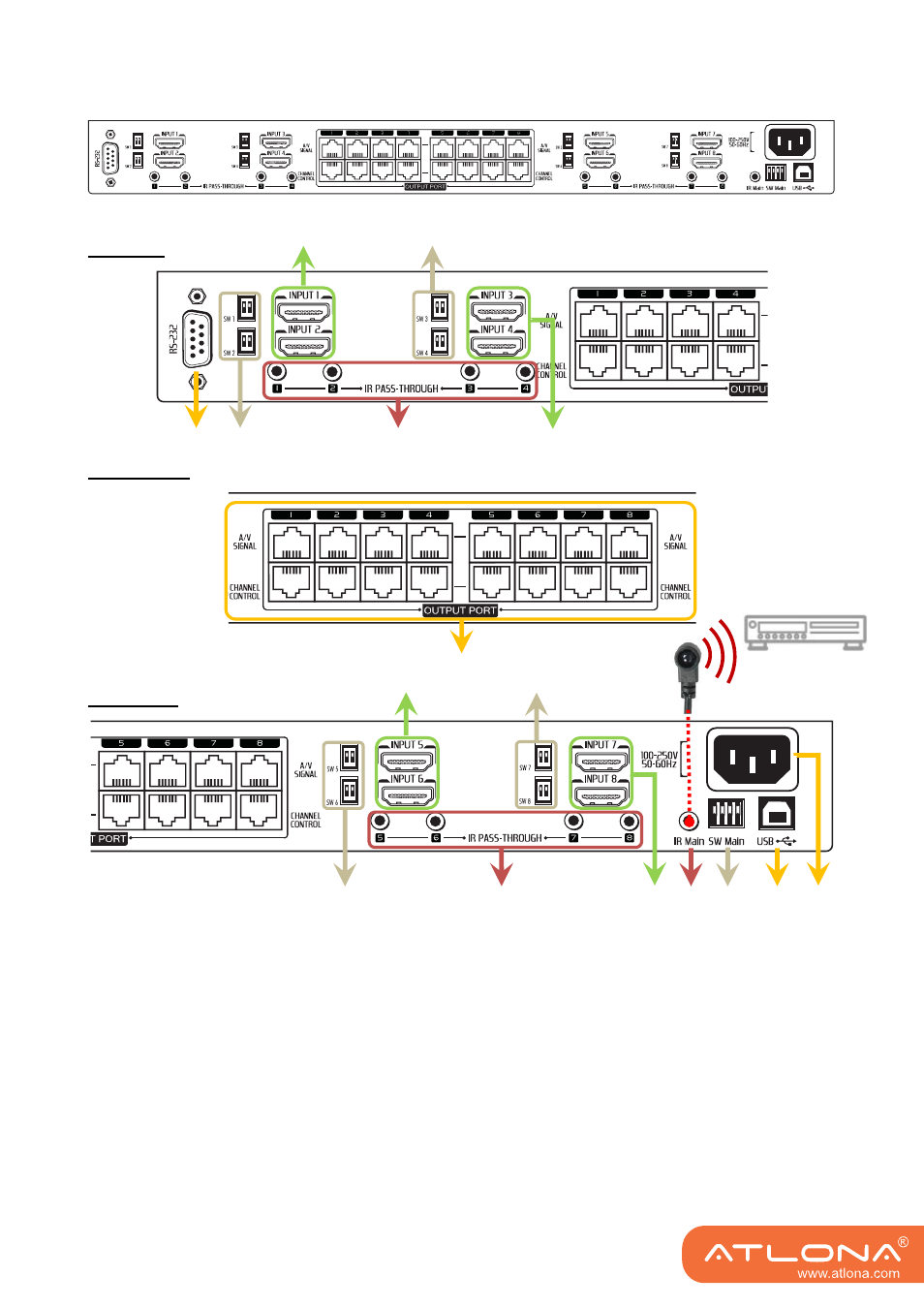
Rear panel overview
Left side
Middle side
Right side
10. RS-232: RS-232 serial control port to connect to a PC for channel control and firmware update
11. SW 1 – SW 8: 2-pin DIP switch (see DIP Switch section in p.8)
12. INPUT 1 – INPUT 8: HDMI
™
inputs that connect to HDMI
™
source devices
13. IR PASS-THROUGH 1 – 8: 3.5mm IR blaster socket for individual HDMI
™
source control
14. OUPUT PORT 1 – 8: dual RJ-45 outputs for each output channel that connect to each matrix
receiver
15. IR Main: 3.5mm IR blaster socket for HDMI
™
source control on all 8 inputs [default socket for
IR blaster]
16. SW Main: 4-pin DIP switch (see DIP Switch section in p.8)
17. USB: USB control port to connect to a PC for channel control
18. 100-250V 50-60Hz AC Power: Connect to a power outlet with the C13 power cord
10
11
12
12
13
11
14
11
11
12
12
13
15
17
18
16