Control ports - ir control – CUE smartCUE User Manual
Page 14
User Manual Interfaces
www.cuesystem.com
Page 14 of 44
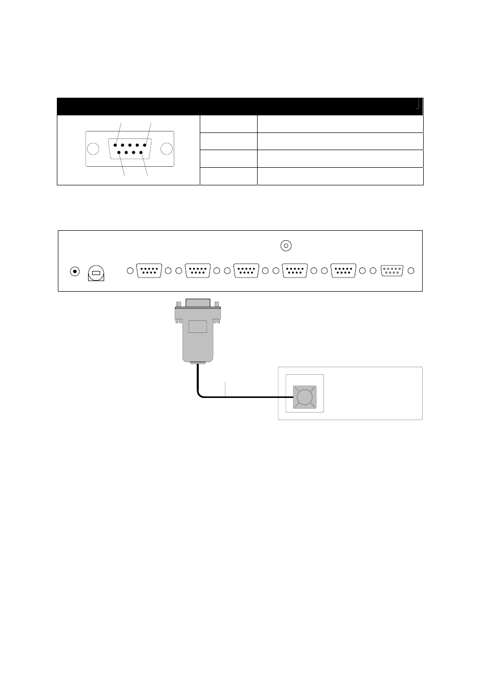
5.3.4. Control Ports - IR Control
Pins used for IR control are described in the table below.
CONTROL PORT 1 - 4, (4) DB-9-male connectors
Pin 1, 2, 3
Not used
Pin 4
IR output
Pin 5
Ground
1
5
6
9
Pin 6, 7, 8, 9
Not used
The IR Adapter /s (CS0110) serves as IR signal emitting device. The emitter must be fixed onto
receiving window on the surface of controlled equipment using two sided adhesive tape.
GND
DATA OUT
DATA IN
DC IN
24V
CHANNEL A
CHANNEL B
CHANNEL C
CHANNEL D
FUSE
1 A
Controlled Device
IR sensor
IR Adapter /s
Parameters of the cable for IR Adapter /s prolongation are
• Maximal
length
70 m using cable 100 pF/m.
• The total cable capacity can be maximal 7 nF.
• The lowest load resistance can be 50 Ω.
• Use 2-core screened cable or twist.