Control ports - serial control – CUE smartCUE User Manual
Page 16
User Manual Interfaces
www.cuesystem.com
Page 16 of 44
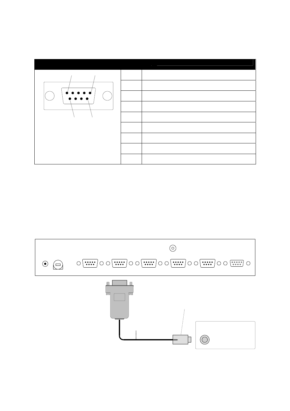
5.3.5. Control Ports - Serial Control
Pins used for serial control RS-232/422/485 are described in the table below.
CONTROL PORT 1 - 4, (4) DB-9-male connectors
Pin 1
Not used
Pin 2
Serial data input (data to smartCUE)
Pin 3
Serial data output (data from smartCUE)
Pin 4
DTR output
Pin 5
Ground
Pin 6
DSR input
Pin 7
RTS output
Pin 8
CTS input
1
5
6
9
Pin 9
Not used
The serial cable can be ordered directly as a Serial IO Cable /s (CA0110) and the controlled
Equipment Name, Type and Manufacturer. For the equipment embedded in the latest Equipmnt.clb
library just this specification is enough, because the Equipment.clb is installed with Cue Director and it
can be checked using Cue Library Director.
For the equipment which is not in the Equipmnt.clb the connector type and pin description including
male / female information is necessary. This information as well as communication protocol is usually
part of the controlled device User Manual.
The serial cable is in many cases part of the accessories of controlled equipment. Usually it is
intended for the direct PC control and it can be used in most cases for smartCUE connection.
GND
DATA OUT
DATA IN
DC IN
24V
CHANNEL A
CHANNEL B
CHANNEL C
CHANNEL D
FUSE
1 A
Controlled Device
Serial IO Cable /s
Connector depends
on a controlled device