Front panel description, Overview, Indicators – CUE smartCUE User Manual
Page 35: Buttons, Switches
User Manual Interfaces
www.cuesystem.com
Page 35 of 44
8.3. Front Panel Description ..............................................
8.3.1. Overview
0
5
4
3
1
2
6
7
8
9
TE
ST
RE
SE
T
AD
DR
ES
S
DA
TA
O
.K
.
auxCUE
AU
X
1
AU
X
2
AU
X
3
AU
X
4
AU
X
5
AU
X
6
AU
X
7
AU
X
8
AU
X
9
AU
X
10
AU
X
11
AU
X
12
AU
X
13
AU
X
14
AU
X
15
AU
X
16
12 13 14 15
6
7
8
9
10 11
5
4
3
2
1
16
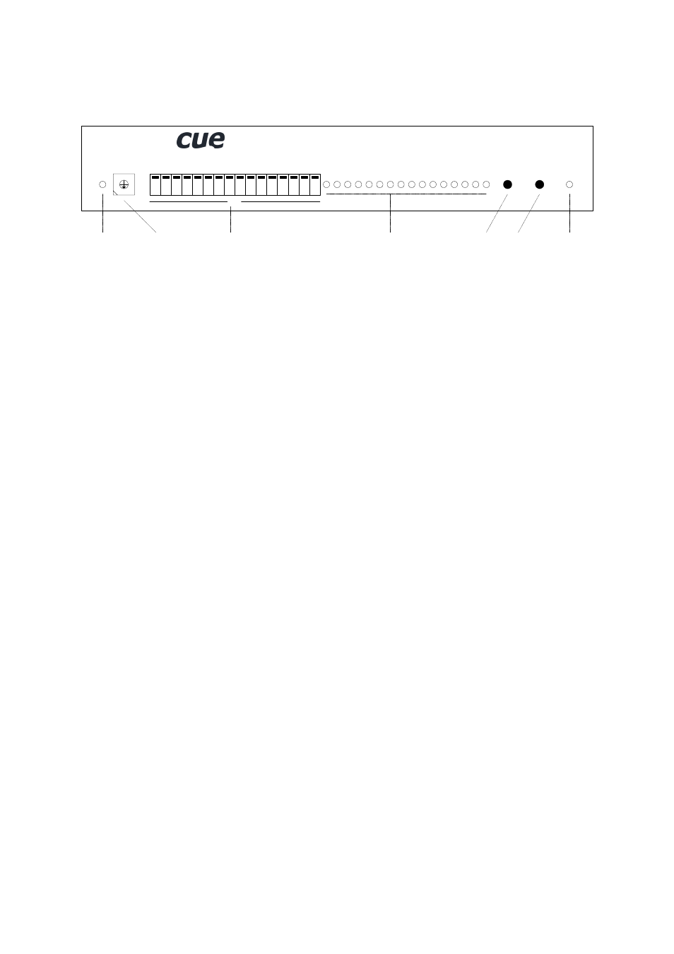
N.
C.
Data
Indicator
Address
Selector
Test
Button
Reset
Button
Power Supply
Indicator
Relay 1 to 16
On / Off Indicators
Relay 1 to 16
Test and Normal Open / Normal Close Switches
8.3.2. Indicators
DATA O.K.
This LED diode is blinking if the interface received correctly the data coming from the CUEring. This
LED blinks OK by Morse after power on, if auto-diagnostic runs correctly.
POWER
Power diode indicates that the interface is powered up.
8.3.3. Buttons
TEST
This button serves for switching over to the testing mode. A detailed description of the testing you can
find in the chapter Diagnostic.
RESET
This button serves for resetting of the interface. During normal operation it is not being used, it solely
serves for testing purposes.
8.3.4. Switches
SWITCH 1 to 16
The switches NO / NC marked 1 to 16 allow to connect NC or NO contact to relay output pin on the
output connector separately for each relay - see relay functional diagram.
• Switch position UP - Normal Open Mode
• Switch position DOWN - Normal Close Mode
By changing over the position of the switches always the position of the output is changing, so you can
use this switches to test connected devices.