Setup by dip switch, Diagnostic, Level 1 – CUE smartCUE User Manual
Page 37: Level 2, Level 3
User Manual Interfaces
www.cuesystem.com
Page 37 of 44
8.4. Setup by DIP Switch...................................................
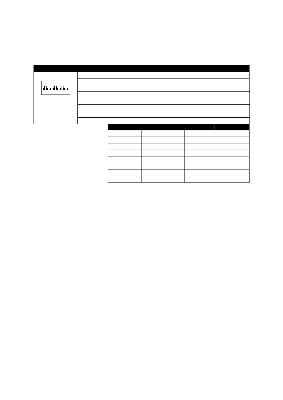
DIP-8 switch is located on the bottom side of the interface. It serves for BANK settings - see the table
below.
Switch view
Switch nr.
Function
1 Not
used
2 Not
used
3 Not
used
4
OFF for standard operation
5
OFF for standard operation
6
BANK bit 2
7
BANK bit 1
ON
1 2 3 4 5 6 7 8
8
BANK bit 0
BANK
Switch 6
Switch 7
Switch 8
0 OFF
OFF
OFF
1 OFF
OFF
ON
2 OFF
ON
OFF
3 OFF
ON
ON
4 ON
OFF
OFF
5 ON
OFF
ON
6 ON
ON
OFF
7 ON
ON
ON
8.5. Diagnostic ..................................................................
8.5.1. Level 1
Level 1 diagnostics runs automatically when the auxCUE is powered on or after reset. It checks
internal microcontroller circuitry. When the tests are running correctly then the DATA O.K. LED starts
blinking (by the Morse signal OK). After that the auxCUE is ready for normal operation.
8.5.2. Level 2
If you keep pressed TEST button, then the testing cycle is operating automatically for all relays. The
processor in the loop is successively switching on all relays, the number of the simultaneously
switched on relays depends on the position of the switch ADDRESS.
8.5.3. Level 3
If you connect the testing adapter (connector DB-9-male which makes shortage between pins 2 and 3)
to the connector DATA IN, you keep the button TEST pressed and then release RESET button. The
auxCUE interface sends the message itself, receives the message via the interconnection in the
testing adapter evaluates and executes it out (successive switching on of all relays). The switching
over into the operating mode is done by pressing button RESET or switching off and on the power.