Control ports – CUE smartCUE User Manual
Page 33
User Manual Interfaces
www.cuesystem.com
Page 33 of 44
8.2.4. Control Ports
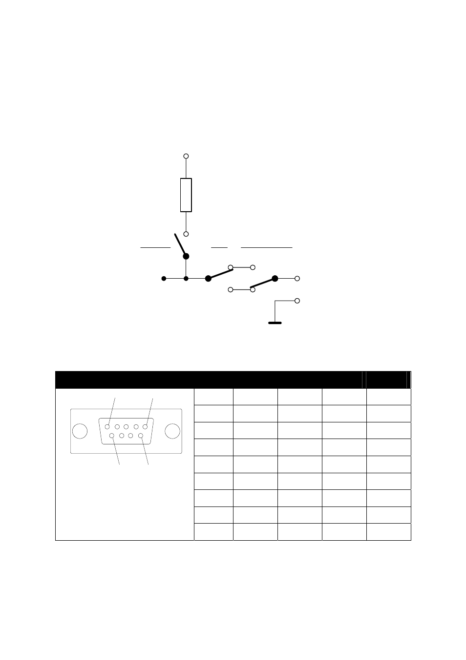
The auxCUE has (16) relay outputs. Each relay can be set to Normal Close (NC) or to Normal Open
(NO) mode by switches on the front panel. Pull-up resistors connected to +15 VDC are switched by
DIP switches located on the bottom panel.
For better understanding of the relay and switches connection see picture below.
Resistor
1.5 kohm
+15 VDC
Relay in
pin 6, 7, 8, 9
Relay out
pin 1, 2, 4, 5
Relay
Front panel switch
NC
NO
ON
OFF
DIP switch
Ground
pin 3
All relays are connected on (4) DB-9-female connectors marked RELAY 1 - 8, RELAY 9 - 16, RELAY
17 - 24 and RELAY 18 - 32. For details see table below.
AUXILIARY 1 - 16, (4) DB-9-female connectors
AUX 1 - 4
AUX 5 - 8
AUX 9 - 12
AUX 13 - 16
Pin 1
Relay 1 out
Relay 5 out
Relay 9 out
Relay 13 out
Pin 2
Relay 2 out
Relay 6 out
Relay 10 out
Relay 14 out
Pin 3
Ground Ground Ground Ground
Pin 4
Relay 3 out
Relay 7 out
Relay 11 out
Relay 15 out
Pin 5
Relay 4 out
Relay 8 out
Relay 12 out Relay 16 out
Pin 6
Relay 1 in
Relay 5 in
Relay 9 in
Relay 13 in
Pin 7
Relay 2 in
Relay 6 in
Relay 10 in
Relay 14 in
Pin 8
Relay 3 in
Relay 7 in
Relay 11 in
Relay 15 in
1
5
6
9
Pin 9
Relay 4 in
Relay 8 in
Relay 12 in
Relay 16 in