Vga connector com connector – NEXCOM VMC 3000/ 3001 User Manual
Page 103
Copyright © 2012 NEXCOM International Co., Ltd. All rights reserved
87
VMC 3000/4000 Series User Manual
Chapter 5: Jumpers and Connectors for VMC 4000 Series
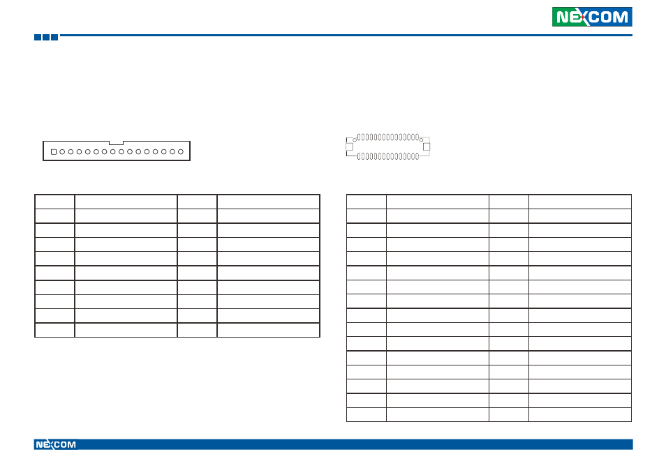
VGA Connector
Connector size: 1x16 16-pin header
Connector location: J8
Pin
Definition
Pin
Definition
1
VGA_GND
2
VGA_+5V
3
VGA_CLK
4
VGA_DATA
5
VGA_VS
6
VGA_HS
7
VGA_GND
8
VGA_GND
9
VGA_GND
10
RGB_GND
11
VGA_BLUE
12
RGB_GND
13
VGA_GREEN
14
RGB_GND
15
VGA_RED
16
NC
MH1
GND
MH2
GND
1
16
1
16
COM Connector
Connector size: 2x15 30-pin header
Connector location: CN1
1
29
2
30
Pin
Definition
Pin
Definition
1
USBPWR_1PPS
2
USBP_ODOMETER
3
USBGND_DIRECTION
4
USBN_GPIO22_GPS
5
SP_TXD_3
6
SP_RXD_3
7
SP_DCD_2
8
COM3_GND
9
COM2_TXD_+
10
COM2_RXD_-
11
COM2_GND
12
SP_DTR_2
13
COM2_RTS_+
14
SP_DSR_2
15
SP_RI_2
16
COM2_CTS_-
17
SP_DCD_1
18
SP_RXD_1
19
SP_TXD_1
20
SP_DTR_1
21
COM1_GND
22
SP_DSR_1
23
SP_RTS_1
24
SP_CTS_1
25
COM_RI_PWR
26
COM_CH_GND
27
NC
28
NC
29
NC
30
NC