Canbus input connector canbus output connector – NEXCOM VMC 3000/ 3001 User Manual
Page 86
Advertising
Copyright © 2012 NEXCOM International Co., Ltd. All rights reserved
70
VMC 3000/4000 Series User Manual
Chapter 5: Jumpers and Connectors for VMC 4000 Series
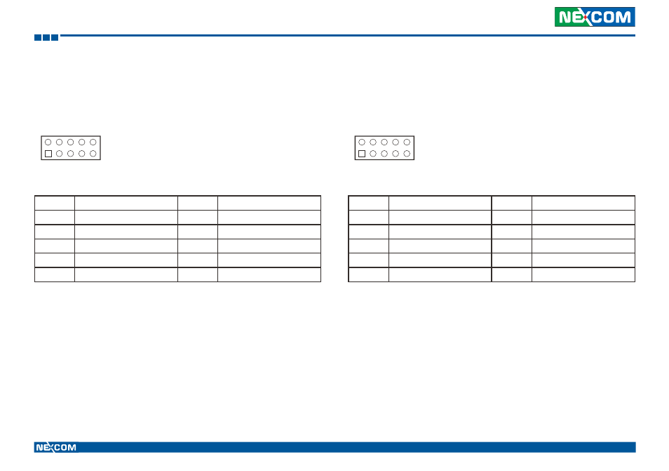
CANbus Input Connector
Connector size: 2x5 10-pin header
Connector location: JP3
1
9
2
10
Pin
Definition
Pin
Definition
1
CAN_TXD
2
CAN_RXD
3
CAN_DI
4
CAN_DO
5
GND
6
GND
7
NC
8
NC
9
VCC_CAN
10
CAN_12V
CANbus Output Connector
Connector size: 2x5 10-pin header
Connector location: JP2
1
9
2
10
Pin
Definition
Pin
Definition
1
CAN1_H
2
C1708_1_H
3
CAN1_L
4
C1708_1_L
5
GND
6
GND
7
NC
8
NC
9
NC
10
NC
Advertising