Com1 ri/power switch vga connector – NEXCOM VMC 3000/ 3001 User Manual
Page 90
Advertising
Copyright © 2012 NEXCOM International Co., Ltd. All rights reserved
74
VMC 3000/4000 Series User Manual
Chapter 5: Jumpers and Connectors for VMC 4000 Series
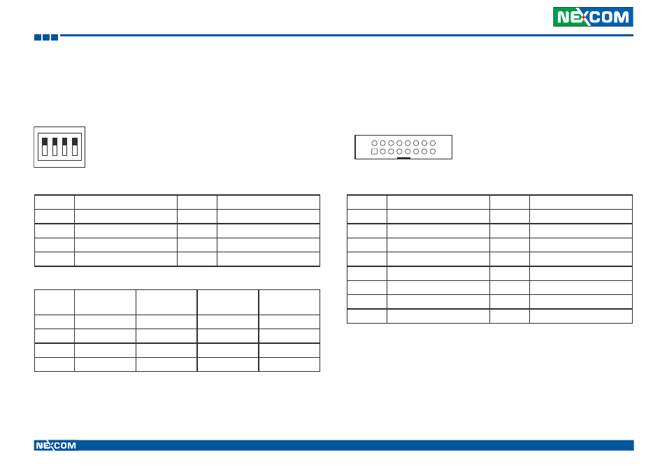
COM1 RI/Power Switch
Connector size: 4-pin DIP switch
Connector location: SW2
1
O
N
2 3 4
Pin
Definition
Pin
Definition
1
COM_12V
2
COM_5V
3
SP_RI_1
4
GND
5
COM_RI_PWR
6
COM_RI_PWR
7
COM_RI_PWR
8
COM_RI_PWR
Pin
12V
5V
RI
(*)
GND
SW2.1
ON
OFF
OFF
OFF
SW2.2
OFF
ON
OFF
OFF
SW2.3
OFF
OFF
ON
OFF
SW2.4
OFF
OFF
OFF
ON
(*) Default Setting
VGA Connector
Connector size: 2x8 16-pin header
Connector location: CN6
1
2
15
16
Pin
Definition
Pin
Definition
1
VGA_RED
2
VGA_GREEN
3
VGA_BLUE
4
VGA_GND
5
VGA_GND
6
RGB_GND
7
RGB_GND
8
RGB_GND
9
VGA_+5V
10
VGA_GND
11
VGA_GND
12
VGA_DATA
13
VGA_HS
14
VGA_VS
15
VGA_CLK
16
NC
Advertising