NEXCOM VMC 3000/ 3001 User Manual
Page 31
Copyright © 2012 NEXCOM International Co., Ltd. All rights reserved
15
VMC 3000/4000 Series User Manual
Chapter 1: Product Introduction
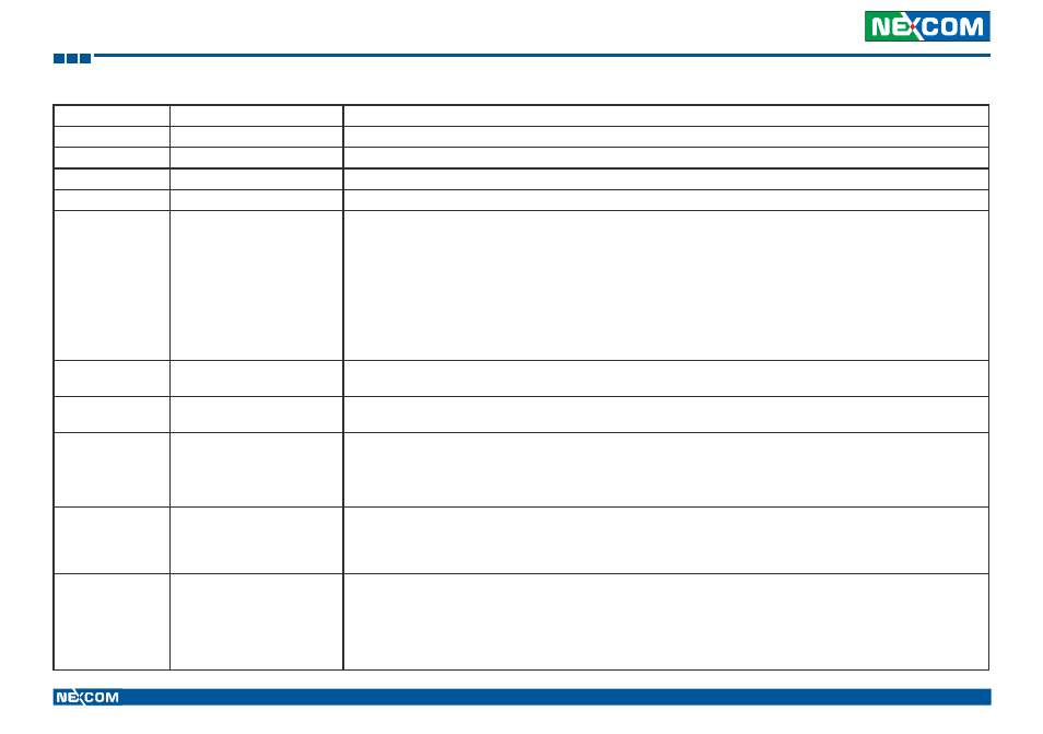
Item
Function
Description
12, 20, 27, 35
Power Input Connector
9 ~ 36VDC power Input.
13, 21, 34, 41
SMBus, 5V/12V Power Output SMBus, power output from vehicle power 5V@1A & 12V@1A DC output
14, 26, 40
COM1
DB9 RS-232 connector with either 0, 5 or 12V on pin 9 for external devices
15
COM2
DB9 RS-232 connector
16, 22, 33
CAN/ GPIO
VMC3000 Series
CAN and GPIO connector,
Default: 3 x GPI and 3 x GPO
Option 1: 1 x CAN bus module, 2 x GPI and 2 x GPO
Option 2: 2 x CAN bus module
VMC4000 Series
CAN and GPIO connector,
Default: CAN Bus
Option: 1 x CAN bus module, 2 x GPI and 2 x GPO
17, 24, 30, 37
USB Port
The USB port complies with USB 2.0 specifications. (VMC 3000 Series)
Dual USB port complies with USB 2.0 specifications. (VMC 4000 Series)
18, 25, 28, 29, 38
LAN Port
The LAN port is an RJ45 interface with integrated LEDs and supports 10/100/1000Mbps Ethernet data transfer rates.
The LAN port supports 10/100/1000Mbps Ethernet data transfer rates.
19, 23, 32, 36
Audio
Line-out
Line-out is a stereo output for connecting external speakers.
Mic-in
Mic-in receives monophonic input from an external microphone.
31
Multi I/O port
Integrate the following COM interface
- 1 x COM for RS-232/422/485 (default RS-232)
- 1 x COM for RS-232 TX/RX
- 1 x RS-232 with either 0, 5 or 12V on pin 9 for external devices
39
Multi I/O port
Integrate the following interface
- 1 x COM for RS-232/422/485 (default RS-232)
- 1 x COM for RS-232 TX/RX
- 1 x GPIO (2 x DI, 2 x DO)
- 2 x CAN Bus
- 1 x DB9 for RS-232 full