Locations of the jumpers and connectors, Carry board – NEXCOM VMC 3000/ 3001 User Manual
Page 75
Copyright © 2012 NEXCOM International Co., Ltd. All rights reserved
59
VMC 3000/4000 Series User Manual
Chapter 5: Jumpers and Connectors for VMC 4000 Series
I24
E36
I26
I25
DU25
DU24
DU27
DU26
M22
S568 D392 D394 S569
S583 S582
DO9
I28
D2
I21
V82
I23
I22
K7
K6
V36
S426
S374
TX2
V6
I8
K26
N3
I3
I4
V3
V62
D72
D73
D75
D71
FTE8
DO6
V54
DO7
I2
I9
I7
KQ2
UPVDI
SFTFU
TQFBL`S
35
24
36
23
47
48
59
2
86
87
61
62
211
36
37
2
35
36
23
24
SUD
2.3!!Opsnbm
3.4!!Dmfbs!DNPT
NFNCSBOF
47
48
2
59
91!QPSU
75
4:
NDV!DPO
76
49
44
43
2
213
239
2
75
76
:7
:8
214
3
2
6
2
2
5
2
6
63
2
62
29 27
28 26
6
NI7
2
4
9
31
2
2
B221
B2
41
2
C221
C2
21
D221
D2
E221
2
4
2
21
:
28
26
27
23
29
2
3
2
3
2
C22
C23
62
63
5
2
2
C2
8
WFS;D
2
21
2
3
2
C43
:
2
7
NBEF!JO!UBJXBO
5CWD4111D7Y21
WNDC4111.DBD2
2:
31
2
7
2
5
2
2
3
J15
J1
JP9
CN1
SW1
JP2
J7
J8
J13 JP6
JP7
CN9
J9
SW6
JP8
J16
CN8
JP5
SW2
J6
JP1
J4
CN7
CN3
J12
CN5
CN6
CN12
SW3
JP3
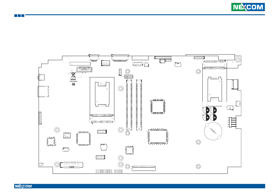
Carry Board
Locations of the Jumpers and Connectors
The figure below is the carry board used in the VMC system. It shows the locations of the jumpers and connectors.