Gpio1.2/can2 mode selection – NEXCOM VMC 3000/ 3001 User Manual
Page 94
Advertising
Copyright © 2012 NEXCOM International Co., Ltd. All rights reserved
78
VMC 3000/4000 Series User Manual
Chapter 5: Jumpers and Connectors for VMC 4000 Series
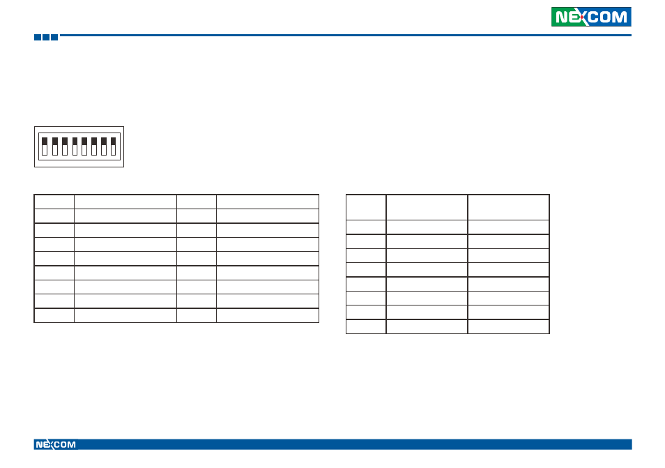
GPIO1.2/CAN2 Mode Selection
Connector size: 8-pin DIP switch
Connector location: SW1
Pin
GPIO1.2
(*)
CAN2
SW1.1
ON
OFF
SW1.2
OFF
ON
SW1.3
ON
OFF
SW1.4
OFF
ON
SW1.5
ON
OFF
SW1.6
OFF
ON
SW1.7
ON
OFF
SW1.8
OFF
ON
(*) Default Setting
1
O
N
2 3 4 5 6 7 8
Pin
Definition
Pin
Definition
1
GAL_GPO1_R
2
C1708_2_L
3
GAL_GPO2_R
4
C1708_2_H
5
GAL_GPI2_R
6
CAN2_H
7
GAL_GPI1_R
8
CAN2_L
9
GPI1_CANL
10
GPI1_CANL
11
GPI2_CANH
12
GPI2_CANH
13
GPO2_C1708H
14
GPO2_C1708H
15
GPO1_C1708L
16
GPO1_C1708L
Advertising