External i/o interface, Vmc 4000 – NEXCOM VMC 3000/ 3001 User Manual
Page 38
Copyright © 2012 NEXCOM International Co., Ltd. All rights reserved
22
VMC 3000/4000 Series User Manual
Chapter 1: Product Introduction
External I/O Interface
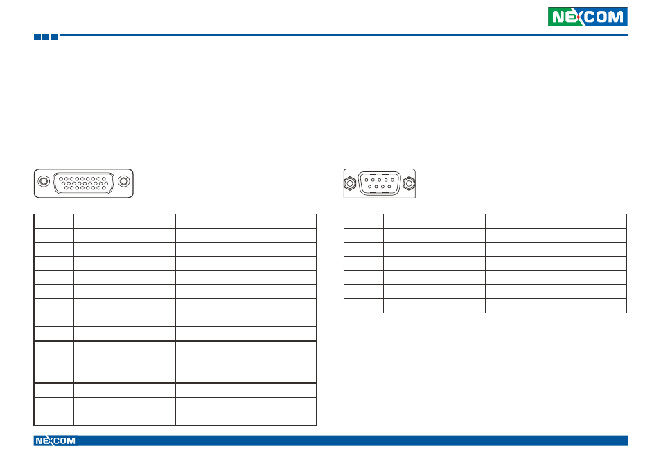
VMC 4000
RS-232/422/485 (COM2), RS-232 (COM3), CAN Bus and GPIO Connector
Connector size: DB-26 female port, 26-pin D-Sub
Connector location: J3
Pin
Definition
Pin
Definition
1
SP_RI_2
15
C1708_2_L
2
SP_DTR_2
16
GAL_GPI2_R
3
COM2_CTS_-
17
GAL_GPO2_R
4
CAN_GPS
18
SP_RXD_3
5
CAN_ODOMETER
19
SP_DSR_2
6
C1708_2_H
20
SP_DCD_2
7
GAL_GPI1_R
21
COM2_GND
8
GAL_GPO1_R
22
CAN_GND
9
SP_TXD_3
23
CAN_GPIO22
10
COM2_TXD_+
24
CAN_DIRECTION
11
COM2_RTS_+
25
GAL_GPIO_GND
12
COM2_RXD_-
26
COM3_GND
13
CAN1_H
MH1
CH_GND
14
CAN1_L
MH2
CH_GND
Pin
Definition
Pin
Definition
1
SP_DCD_1
7
SP_RTS_1
2
SP_RXD_1
8
SP_CTS_1
3
SP_TXD_1
9
COM_RI_PWR
4
SP_DTR_1
MH1
CH_GND
5
COM1_GND
MH2
CH_GND
6
SP_DSR_1
COM1 RS-232 Connector
Connector size: DB-9 male port, 9-pin D-Sub
Connector location: CN7
1
9
19
26
1
5
6
9