General, Section 2 • controls and indicators -1, General -1 – Basler Electric BE1-87G User Manual
Page 21: Figure 2-1. controls and indicators -1, Table 2-1. control and indicator descriptions -1
SECTION 2 • CONTROLS AND INDICATORS
GENERAL
BE1-87G controls and indicators are illustrated in Figure 2-1 and described in Table 2-1.
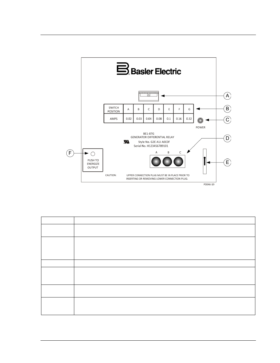
Figure 2-1. Controls and Indicators
Table 2-1. Control and Indicator Descriptions
Locator
Description
A
Sensitivity Switch. This thumbwheel switch has seven positions labeled A through G
and sets the desired level of operating current that will cause the relay to trip.
B
Switch Position Chart. This chart relates the switch position to the operating current
required for tripping when the restraint current is less than or equal to the nominal
value of sensing current (5 Aac for sensing input range 1 or 1 Aac for sensing input
range 2).
C
Power Indicator. This LED lights when operating power is applied to the relay.
D
Target Indicators. Electronically-latching red target LEDs light when a trip condition
exists on the corresponding phase of current. When the optional targets are specified,
a target LED is provided for each phase protected.
E
Target Reset Switch. Operating this switch resets all of the target indicators (locator
D).
F
Output Test Switch. This momentary-action pushbutton switch operates the output and
auxiliary relays. The switch is accessed by inserting a ⅛” diameter, non-conducting rod
through the access hole in the front panel.
9170800990 Rev N
BE1-87G Controls and Indicators
2-1