Band-pass filters, Band-pass filters -2 – Basler Electric BE1-87G User Manual
Page 26
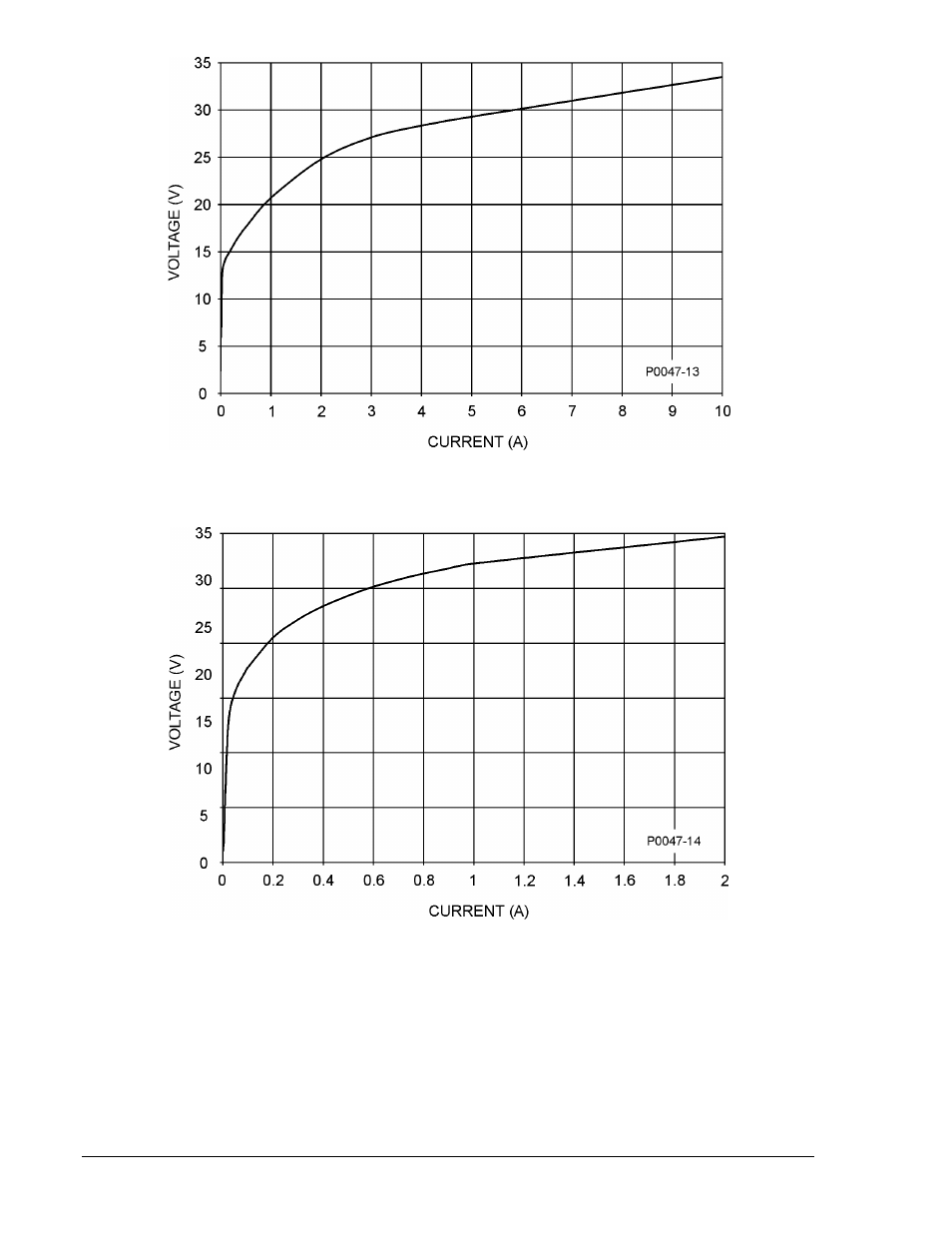
Figure 3-2. Stabilizing Reactor Impedance Characteristic, Sensing Input Range 1
Figure 3-3. Stabilizing Reactor Impedance Characteristic, Sensing Input Range 2
Band-Pass Filters
The outputs of the relay’s internal transformers are filtered to eliminate the third harmonic and minimize
the effect of dc offset caused by CT saturation (as may occur during synchronization or asymmetrical
faults). Two band-pass filters are used: difference and sum.
The output of the difference band-pass filter is applied to a full-wave rectifier. The rectifier scales the
differential and applies the output to the comparator as the operating current (I
OP
) signal.
The output of the sum band-pass filter is also applied to a full-wave rectifier. The scaled sum of the two
inputs represents the restraint current (I
R
). The restraint current is scaled for a 50% slope above nominal
input current (5 Aac for sensing input range 1 or 1 Aac for sensing input range 2).
3-2
BE1-87G Functional Description
9170800990 Rev N