Introduction, Be1-87g function blocks, Current sensing inputs – Basler Electric BE1-87G User Manual
Page 25: Stabilizing reactor, Section 3 • functional description -1, Introduction -1, Be1-87g function blocks -1, Current sensing inputs -1, Stabilizing reactor -1, Figure 3-1. function block diagram -1
SECTION 3 • FUNCTIONAL DESCRIPTION
INTRODUCTION
This section describes how the BE1-87G functions and explains its operating features.
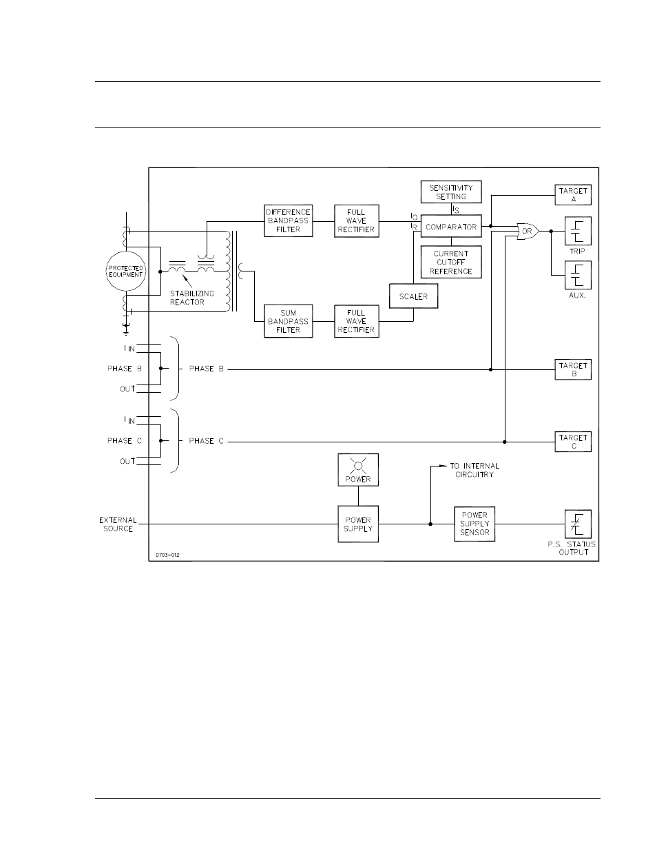
BE1-87G FUNCTION BLOCKS
BE1-87G function blocks are illustrated in Figure 3-1 and described in the following paragraphs.
Figure 3-1. Function Block Diagram
Current Sensing Inputs
Sensing current for each monitored phase is provided by two user-provided, system CTs with secondary
windings that match the BE1-87G’s sensing input range. BE1-87G relays with sensing input range 1 (style
x1x-xxx-xxxx) require CTs with 5 Aac secondary windings. Relays with sensing input range 2 (style x2x-
xxx-xxxx) require CTs with 1 Aac secondary windings. Two CTs are used on each phase—one CT on
each side of the protected machine. Sensing current is applied to internal transformers that provide
system isolation and determine the differential and sum currents. These CTs are gapped to withstand dc
offset.
Stabilizing Reactor
To minimize dissimilar performance of the system CTs, the stabilizing reactor acts as a stabilizing
impedances during external faults. Stabilizing reactors are current rated based on time and ambient
temperature (refer to Section 1, General Information, Specifications). Figures 3-2 and 3-3 illustrate the
stabilizing reactor impedance characteristic.
9170800990 Rev N
BE1-87G Functional Description
3-1