User manual, 2 rear panel, 3 external cable and cord – Bolide SVR9000s MO User Manual
Page 7
User Manual
4
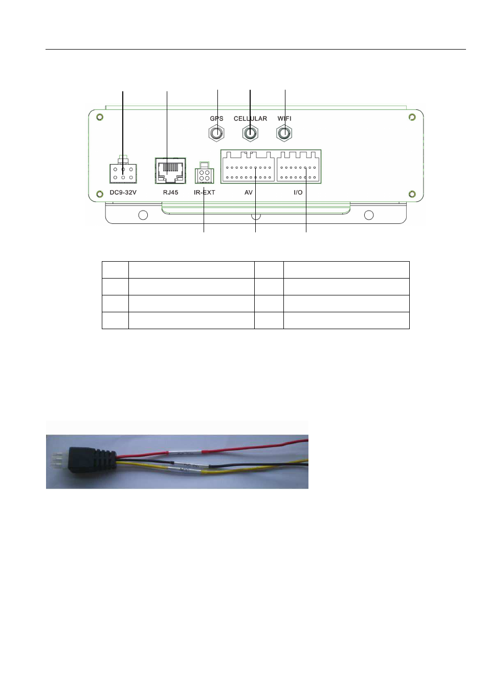
2.2 Rear Panel
1
Power Supply Jack
5
WIFI Antenna Port
2
Ethernet Port
6
IR-Ext input
3
GPS Antenna Port
7
A/V Jack
4
Cellular Antenna Port
8
Sensor I/O Port
2.3 External Cable and Cord
2.3.1 Power Cord
BATT Pin (Red): Power input (connected to car battery+)
GND Pin (Black): Power GND (connected to car battery -)
ACC Pin (Yellow): Ignition signal input (connected to car power level)
The 6-pin plug will be connected to power supply jack of rear panel. Red and black wires connected to car
battery + and – respectively, yellow wire to ignition wire.
Reminder:
1)Make sure the power supply is between 9V and 32V to avoid the device damage due to higher voltage.
2)It is very import for you to make the wires insolated.
3)Yellow wire must be connected to ignition wire, otherwise, the device will not support delay power off
function and you will miss all the video record.
6 7 8
1 2 3 4 5