User manual – Bolide SVR9000s MO User Manual
Page 8
User Manual
5
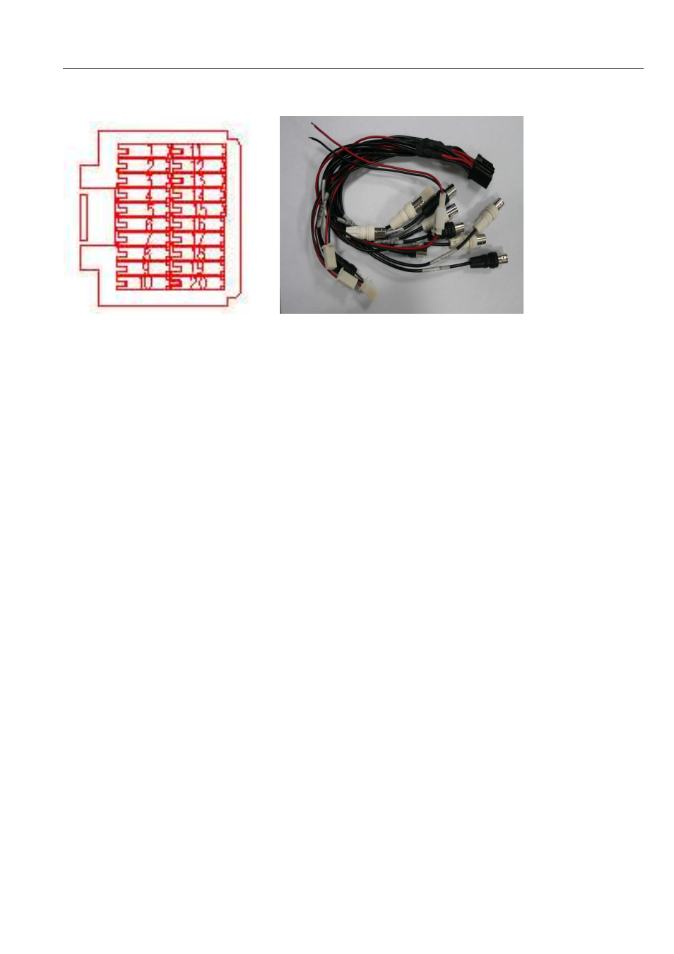
2.3.2 A/V Cable
1. Audio output (white BNC port)
2. Video output (Black BNC port)
3. CH4 Audio input (White BNC port)
4. CH4 Video input (Black BNC port)
5. CH3 Audio input (White BNC port)
6. CH3 Video input (Black BNC port)
7. CH2 Audio input (White BNC port)
8. CH2 Video input (Black BNC port)
9. CH1 Audio input (White BNC port)
10. CH1 Video input (Black BNC port)
11-12. Monitor+12 V power supply output (Red = Positive pole (+); Black = Negative pole (-))
13-14.CH4 Camera+12V power supply output (Red=Positive pole (+); Black = Negative pole (-))
15-16.CH3 Camera+12V power supply output (Red=Positive pole (+);Black = Negative pole (-));
17-18 CH2 Camera + 12V power supply output (Red=Positive pole (+);Black = Negative pole (-))
19-20 CH2 Camera + 12V power supply output (Red=Positive pole (+);Black = Negative pole (-))