Setup, cont’d – BUG-O Systems AGS-4000 User Manual
Page 13
13
SETUP, CONT’D.
2c) INSTALLING BUG-5910 TUBE CARRIAGE
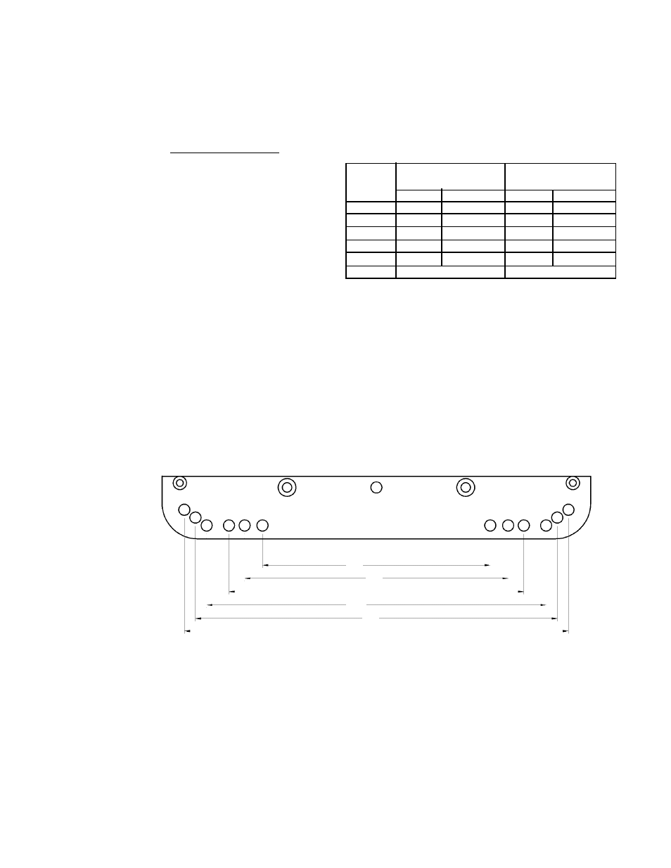
1. Select the correct pair of holes on each side of the carriage for the rail diameter being
used (see chart). If the wheels are not attached to the correct set of holes, remove them
and bolt the wheel brackets in selected holes. Tighten the bolts until the brackets are
snug, but still free to rotate.
2. Use the wheel engagement knob (A)
to open the split carriage. On the drive
unit, loosen and turn the clutch knob
(B) counter clockwise to declutch the
drive pinion.
3. Place the carriage on the rail with the
wheels in the rail grooves. Use the
wheel engagement (A) knob to close
the carriage then move the carriage
back and forth a few inches. The
wheels on their mounting brackets will align themselves correctly in the rail grooves.
4. Verify that the wheels are properly aligned, then tighten the wheel mounting bolts to lock
them in position. Rotate the clutch knob (B) clockwise while gently rocking the carriage
back and forth to engage the drive pinion with the rack.
5. Verify that the pinion is properly engaged in the rack. The correct wheel position will
provide a minimum of 1/8" (3 mm) engagement between the drive pinion and the rack.
NOTE: The pinion height may need to be adjusted for some rail or pipe sizes.
6. Position and clamp the weld gun, cutting torch, cables, etc. and proceed with the
operation.
F
E
D
C
B
A
Carriage
BRR-1210
Wheel
Rail ID
Pipe OD
Hole
Set
in mm in mm
A
20 - 25
500 - 635
9 - 21
230 - 530
B
23 - 35
585 - 890
12 - 31
300 - 790
C
30 - 44
760 - 1120
18 - 40 455 - 1015
D
41 - 60 1040 - 1525 29 - 54 735 - 1375
E
75 - 174 1905 - 4420 64 - 170 1625 - 4320
F
flat rail
flat rail
Note: Chart values are for reference only