Setup, cont’d – BUG-O Systems AGS-4000 User Manual
Page 14
14
SETUP, CONT’D.
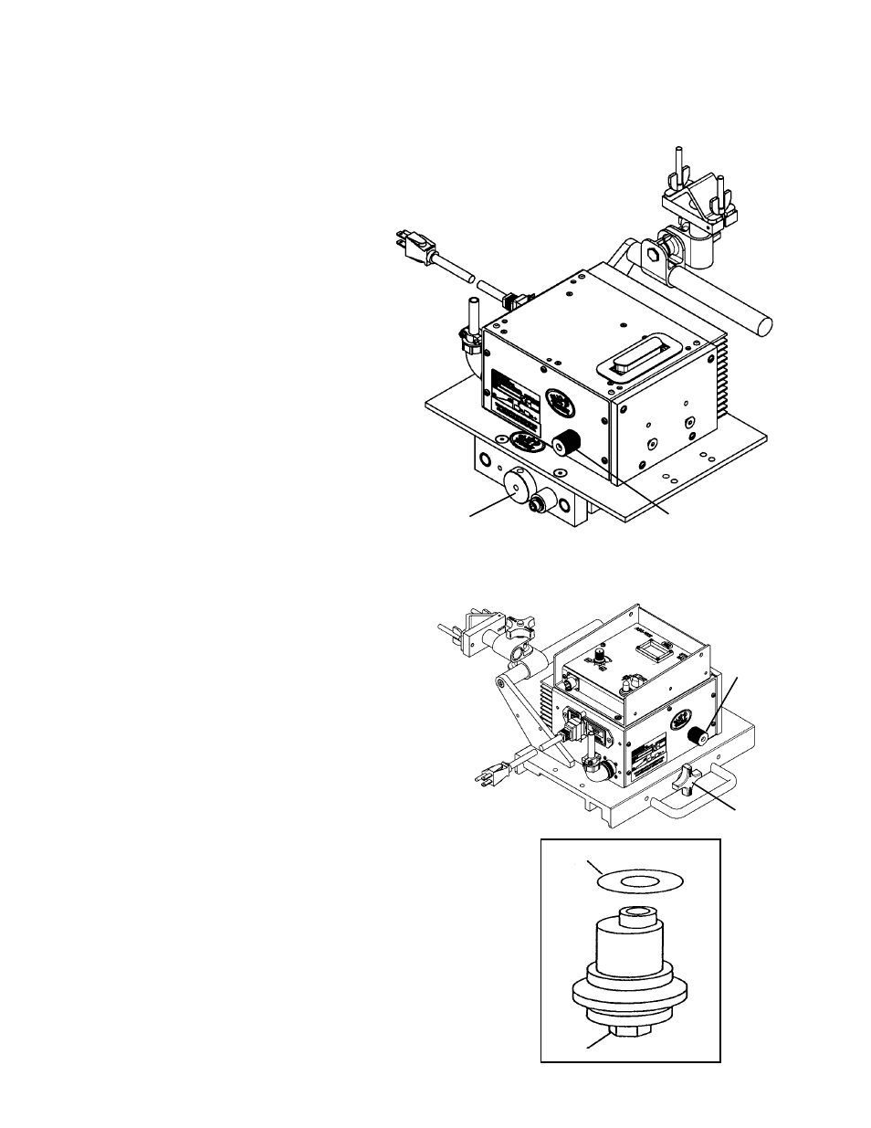
2d) POSITIONING FMD-1105 HI-FLEX CARRIAGE ON TO FMD HI-FLEX RAIL
A
The wheels along one side of the carriage have stainless
steel shim washers
(C) underneath. These wheels are
adjustable. Readjust these wheels (if necessary) by rotating
the hex bolt
(D) with a 1/2" wrench.
Grasp the sides of the carriage. The wheels are too loose if it
is possible to move the carriage from side to side or up and
down. Use a finger to keep one of the adjustable wheels from
rotating as the carriage is manually pushed along the track.
The wheels are too tight if firm finger pressure is not enough
to prevent wheel rotation. Repeat the process for the other
adjustable wheel.
Always check for proper carriage wheel
adjustment before using the machine. Turn
the wheel engagement knob
(A) on the side of
the carriage until the wheels are fully moved
towards the center of the carriage (engaged).
Then rotate the master drive clutch knob
(B) fully counter clockwise to disengage the
drive pinion. Slide the carriage onto the end
of the track. The wheels should slide into the
V-grooves and the carriage will move smoothly
along the track if the wheels are properly
aligned.
C
D
B
A
3) WHEEL ADJUSTMENT AND ALIGNMENT ON ARR, AFR AND BRR RAILS
FMD-1105 Hi-Flex Carriage
The Hi-Flex Carriage has a carrying
capacity of 100 lbs (45 kg). Used ONLY
on Hi-Flex Rail (FMD-1050).
Turn the wheel engagement knob
(A) on the side of the carriage fully
counter clockwise to disengage the
wheels. Then rotate the Master Drive
Unit clutch knob
(B) (below) fully
counter clockwise to disengage the
drive pinion. The carriage can now
be placed anywhere on the track.
Turn the wheel engagement knob
(A)
clockwise to engage the rail firmly in
the V-groove of the bearing wheels.
Manually move the carriage along the
track to verify the motion is smooth and
the wheel alignment is correct. Rotate
the Master Drive Unit clutch knob
(B)
fully clockwise while gently rocking
the machine forward and backward to
engage the drive pinion. The rocking
motion is necessary to help insure
proper gear mesh.
B