BUG-O Systems AGS-4000 User Manual
Page 45
Advertising
45
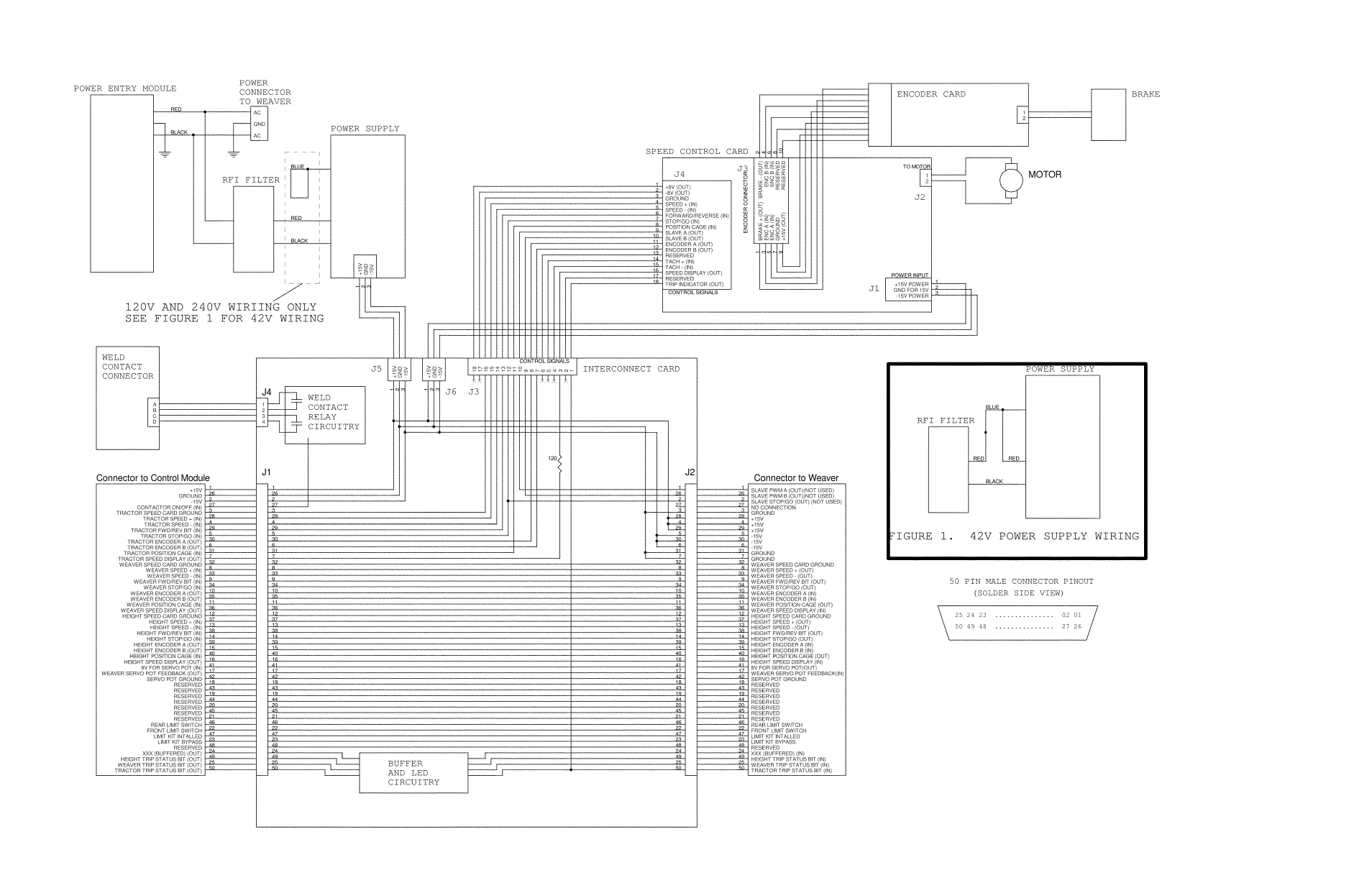
MASTER DRIVE WIRING DIAGRAM MDP-1000/ MDP-1002/ MDP-1004
NOTES:
Encoder card and brake are mounted on the motor.
18 pin connectors are not wired 1:1.
The Connector on one end is flipped.
For example, Pin 1 goes to connector 18.
Most signals on the 50 pin connector come in one 50 pin connector and
exit on the other 50 pin connector.
Pinouts for connectors can be determined from slik-screen.
Advertising
This manual is related to the following products: