23 ....................signal wiring, Signal wiring, Parts list – BUG-O Systems AGS-4000 User Manual
Page 23
23
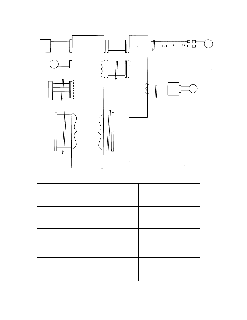
SIGNAL WIRING
PS
WHT/RED
WHT/BLK
WHT/OR
WHT/RED
WHT/BLK
WHT/OR
+ 15 V
GND
- 15 V
+ 15 V
GND
- 15 V
F
RED
BLK
CONTACT
A
PUR
PUR
YEL
YEL
A
B
C
D
1
2
3
4
CI
CONTACT
B
MOTOR
OUT
CK
CHOKE
GEAR
MOTOR
M
RED
BLK
INPUTS
OUTPUTS
FROM
CONTROL
MODULE
50 LINE
RIBBON
INTERCONNECT
PCB 1
50 LINE
RIBBON
TO
OSCILLATOR
OR
ACCESSORIES
POSITION
IN AND
BRAKE
OUT
SPEED
CONTROL
PCB 2
18 LINE
C3
C4
PCB 3
10 LINE
RIBBON
B
POSITION
BRAKE
FAN +
FAN -
SPEED
CARD
SIGNALS
C2
ITEM
DESCRIPTION
PART NUMBER
B
Brake Assembly
WPD-1012
Cl
Contactor Cable Assembly
MPD-1036
C2
DC Power Cable Assembly
MPD-1020
C3
Speed Card Cable Assembly
MPD-1019
C4
Motor Wiring
MPD-1018
CK
Inductor Pot Assembly (Choke)
MPD-1042
F
Fan Assembly
MPD-1009
M
Gear Motor
MPD-1015
PCB1
Interconnect Card
PCB-1010
PCB2
Tractor Speed Card
PCB-1000
PCB3
Position Sensor Card
PCB-1012
PS
Power Supply
(see AC Wiring Diagram)
PARTS LIST