Installation, Mechanical fitting and internal connections – Cloud Electronics 46-120 - CDI-46 User Manual
Page 4
CDI-46 Installation and Setup Guide V1.0
4
Installation
Mechanical fitting and internal connections
Fit the CDI-46 card within the 46-120 host unit according to the instructions below:
1. Disconnect the 46-120 from the AC mains.
2. If the 46-120 is installed in an equipment rack, disconnect all audio and control wiring, remove the unit from the rack and
place on a convenient flat surface.
3. Remove the top cover (10 screws) and orientate the unit with the rear panel towards you.
4. Remove the adhesive label covering the empty connector holes from the rear panel.
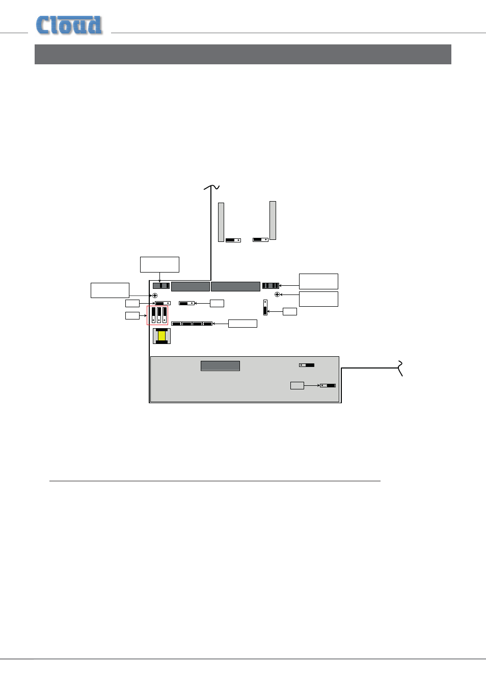
J2
(below sub-board)
LINE INPUT SUB-BOARD
CON21
CON22
CON25
CON23
CON13
REAR LH SECTION OF
46-120 MAIN PCB
NOT TO SCALE – FOR
COMPONENT LOCATION
PURPOSES ONLY
REMOVE M3
SCREW
REMOVE M3
SCREW
REMOVE
JUMPERS
REMOVE
JUMPERS
J7
J10 - J13
J1
J17
J5
5. Refer to the 46-120 main PCB layout diagram above. Note that there are several jumpers on the PCB which will be not
readily accessible once the CDI-46 card is installed (i.e., the card will need to be removed to access them). Therefore
installers should ensure that these jumpers are set as required BEFORE fitting the CDI-46.
Note that J10 to J13 MUST be removed for the CDI-46’s Digital Paging Interface to operate correctly. If the CDI-46 is being
installed purely for remote control purposes (and not paging), they can stay in place.