Cdi-46 jumper settings, Using the digital paging interface – Cloud Electronics 46-120 - CDI-46 User Manual
Page 6
CDI-46 Installation and Setup Guide V1.0
6
CDI-46 jumper settings
The CDI-46 has three PCB jumpers: J1, J2 and J3.
IMPORTANT: It should never be necessary to move any of the CDI-46’s jumpers under normal circumstances.
Installers are strongly advised to contact Cloud’s Technical Dept. at
in the event of a problem.
JUMPER
DESCRIPTION
EFFECT
DEFAULT
J1
PM microphone termination
ON: 46-120 is at end of network “chain”
OFF: Special circumstances only
ON
J2
Forces CDI-46 boot load
mode
OFF: Normal operation
ON: Special circumstances only
OFF
J3
Reset internal NVM memory
OFF: Normal operation
ON: Restores all factory default settings
OFF
Using the Digital Paging Interface
The CDI-46 is fitted with a Cloud Digital Paging Interface; this uses the
CDPM/PM INPUT RJ45 socket. Cloud PM Series
Paging microphones may be connected directly to this socket with Cat 5 cable; the single connection provides all audio, control
and power required by the microphone. (Note that this connector has no LEDs.)
The
CDPM/PM INPUT port is able to supply 250 mA* to power paging microphones. This is adequate to power one or two
microphones of models PM-4, PM-8 or PM-12. Cloud recommend that PM-16 microphones, and all ‘-SA’ models (with spot
announcement sound stores) are powered by a separate, external PSU, as described in the PM Series Installation Guide. (A
suitable PSU is supplied as standard with all ‘-SA’ models.)
As the 46-120 only supports four zones, it is likely that a PM-4 or PM-4SA will be the models most used. If multiple 46-120s are
in use to cover a larger number of zones, the analogue interfaces on the PM and the 46-120 should be used instead. Please refer
to the 46-120 Installation and User Guide for information regarding the use of the analogue interface.
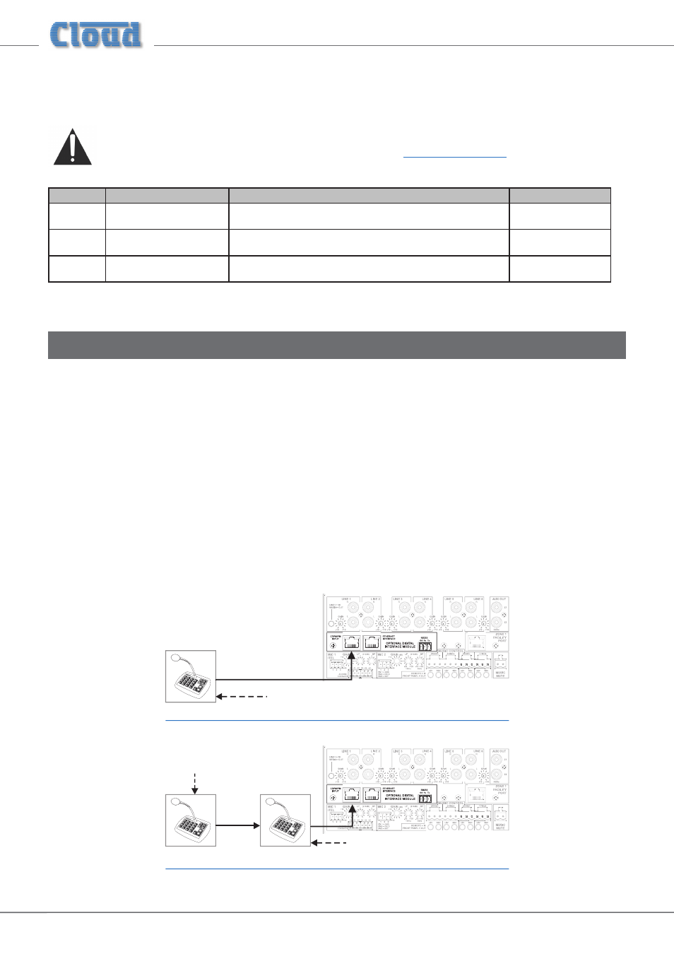
Connect the
OUT socket of the PM Series microphone to the CDPM/PM INPUT socket of the CDI-46 with Cat 5 cable.
If more than one paging microphone is in use – typically at different locations in the building – the microphones should be
“daisy-chained”, with the
OUT socket of one being wired to the IN socket of the next.
46-120
IN
OUT
OUT
46-120
OUT
Termination ON
Termination OFF
Termination
ON
* This figure should be reduced at elevated temperatures by approximately 3 mA/°C above 23°C.