Datatek UTM User Manual
Page 13
U T M U s e r ' s M a n u a l
01/18/08
13
3.2 CABLING
This section provides information on how to cable the UTM console and data ports with the
DTK41 I/O board, or the CEY5 I/O board.
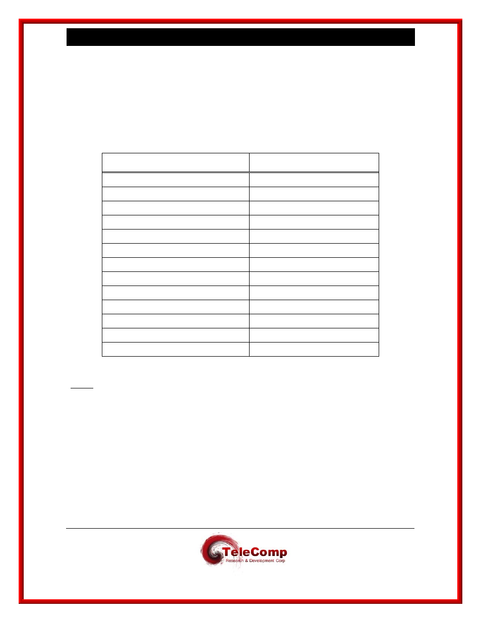
Consult the following table for ordering information regarding all of the cabling options shown in
this section.
Depending upon access availability, the following cables will be needed to setup a UTM console
connection.
Cable / Adapter
Description
258B adapter
50-pin M to 6 8-pin mod
CS25AS-MOD
50-pin 180-M to 34-pin V.35
V.35 to RS-232C adapter
Male 34 pin V.35 to Female DB25
V.35 to RS-232C adapter
Female 34 pin V.35 to Male DB25
T1 crossover modular cable
8-pin mod to 8-pin mod
Mod DB15 adapter
8-pin mod to DB15 M
D8AH-M adapter
25-pin M to mod socket
D8AH-F adapter
25-pin F to mod socket
D8AG-M adapter
25-pin M to mod socket
D8AG-F adapter
25-pin F to mod socket
Console Cable (special wiring)
8-pin mod to 8-pin mod
Straight modular cable
8-pin mod to 8-pin mod
CAT5 modular cable
8-pin mod to 8-pin mod (shielded)
Notes:
Use an AG adapter to talk to a terminal and an AH adapter to talk to a modem.
The AH adapter will be used to terminate the cable and will be attached to the appropriate
device. The attached device will determine the gender of the AH adapter.