D t k 4 1, I/o dsu p – Datatek UTM User Manual
Page 19
U T M U s e r ' s M a n u a l
01/18/08
19
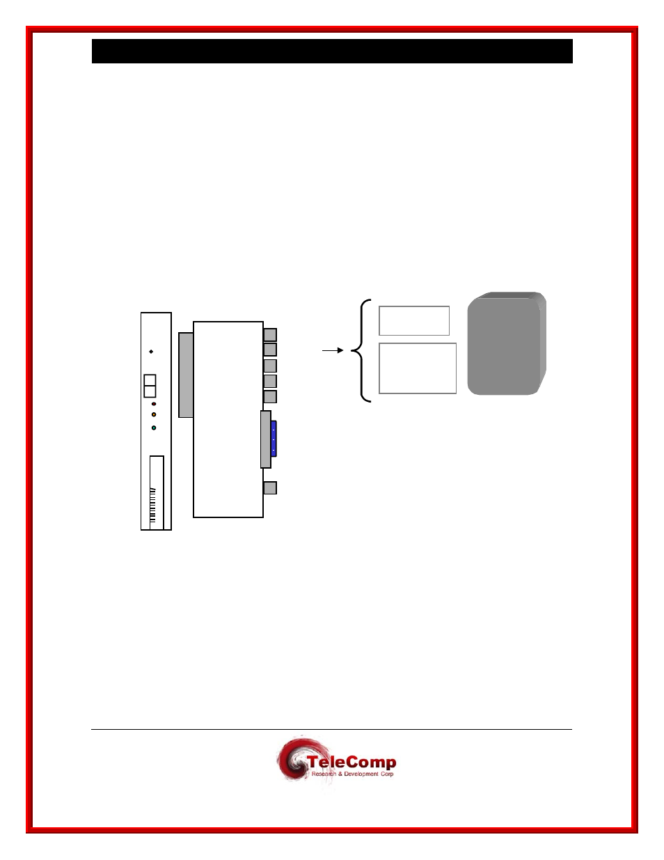
3.6 C
ABLING THE
I/O DSU P
ORT
When the phy option (see module command set) of the trunk command is selected as DSU, the
following will be needed:
A UTM circuit pack and either a DTK41 IO Board, or a CEY5 I/O Board
A T1 crossover modular cable or T1 crossover cable with adapter can be connected to the
DSU port's modular 8-pin modular interface
Option 1: Use the T1 crossover mod cable with a modular 8-pin connector on one end
and an 8-pin modular connector on the other.
Option 2: Use the T1 crossover mod cable with a modular 8-pin connector on one end
and an 8-pin modular connector on the other and add a Mod/DB15 adapter.
Network
Interface
T1 Crossover
Mod Cable
T1 Crossover
Mod cable with
Mod DB15
adapter
LAN #3
DSU
Serial
Console
D
S
P
Q
O
O
Y
A
X
X
Reset
Mode
Enabl
Diag
Disab
Fault
Off
Line
On
Line
Datatek
TN
2524
U T M
D
T
K
4
1
LAN #2
LAN #1
FIBER
LAN