2 2.2 f – Datatek UTM User Manual
Page 7
U T M U s e r ' s M a n u a l
01/18/08
7
2.2 2.2
F
ACEPLATE
2.2.1 L
IGHT
E
MITTING
D
IODES
(LED)
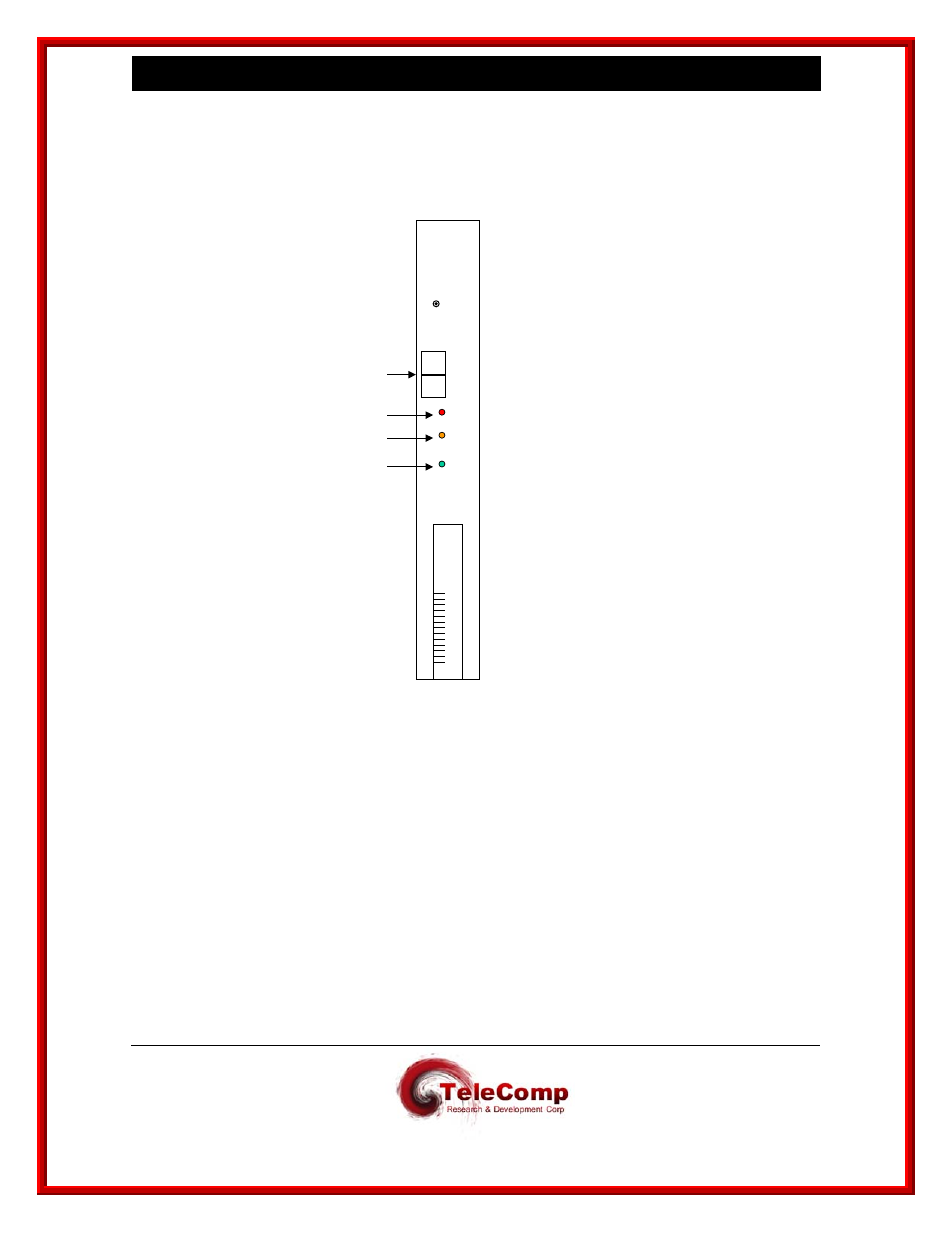
The lights on the module faceplate are green, amber, and red. They indicate on-line, off-line, and
fault states respectively. When the module circuitry detects an on-board fault, the red LED (fault)
is lit.
2.2.2 M
ODE
S
WITCH
The Mode Switch supports three positions: Enabl, Diag and Disab. The Mode switch must be in
the Enabl position for the UTM to function properly.
2.2.3 R
ESET
B
UTTON
When the Reset button is pressed, the module buffers and registers are cleared, and the module
application program is restarted. The module is taken out of service, and all connections are
terminated.
D
S
P
Q
O
O
Y
A
X
X
Reset
Mode
Enabl
Diag
Disab
Fault
Off
Line
On
Line
Red
Yellow
Green
Datatek
Switch
TN
2524
U T M