Jumper settings – DFI EC200 Series User Manual
Page 58
Advertising
58
4
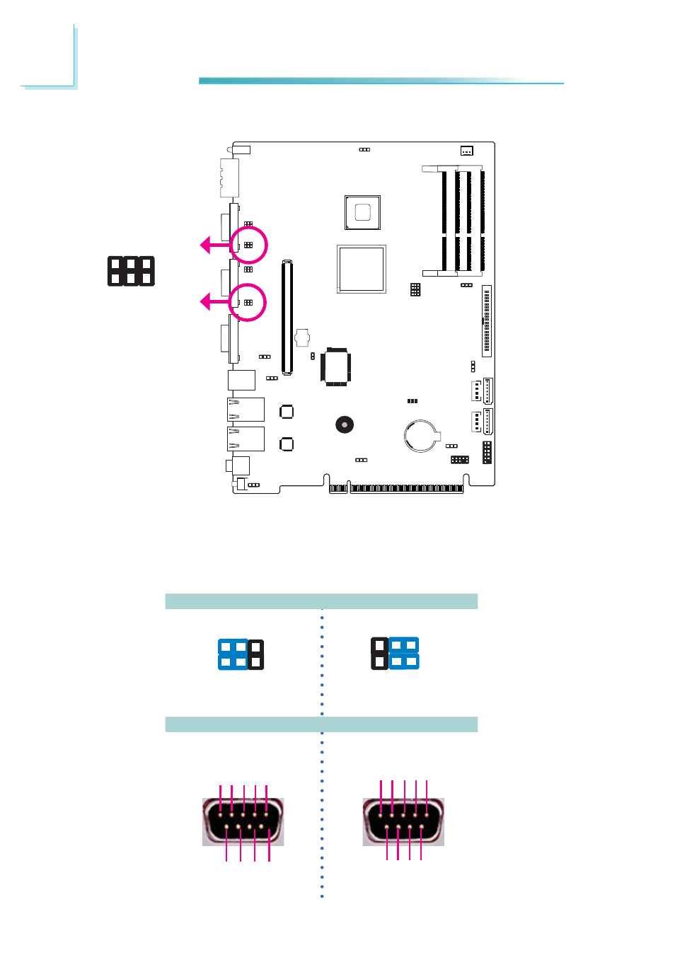
Jumper Settings
VGA
COM1 and COM2 RS232/Power Select
JP12
JP13
1
6
5
2
JP12(COM1) and JP13(COM2) are used to confi gure COM1 and COM2 to pure
RS232 or RS232 with power.
The pin function of COM1 and COM2 will vary according to JP12’s and JP13’s set-
ting respectively.
JP12 / JP13
COM 1 / COM 2
1-3, 2-4 On:
RS232 (default)
6
4
2
5
3
1
3-5(+12V), 4-6(+5V) On:
RS232 with power
6
4
2
5
3
1
DCD
TXD
RXD
DT
R
GND
1 2 3 4 5
6
8 9
7
DSR
CT
S
RT
S
RI
+5V
TD
RD
DT
R
-
GND
1 2 3 4 5
RT
S
-
+12V
DSR
-
CT
S-
6 7 8 9
Advertising
This manual is related to the following products: