Chapter 3 - hardware installation, Board layout, Block diagram – DFI BT968 User Manual
Page 10: A / b, C / d, Atom e3800 series /celeron
www.dfi .com
Chapter 3 Hardware Installation
10
Chapter 3
Chapter 3 - Hardware Installation
Board Layout
Top View
Bottom View
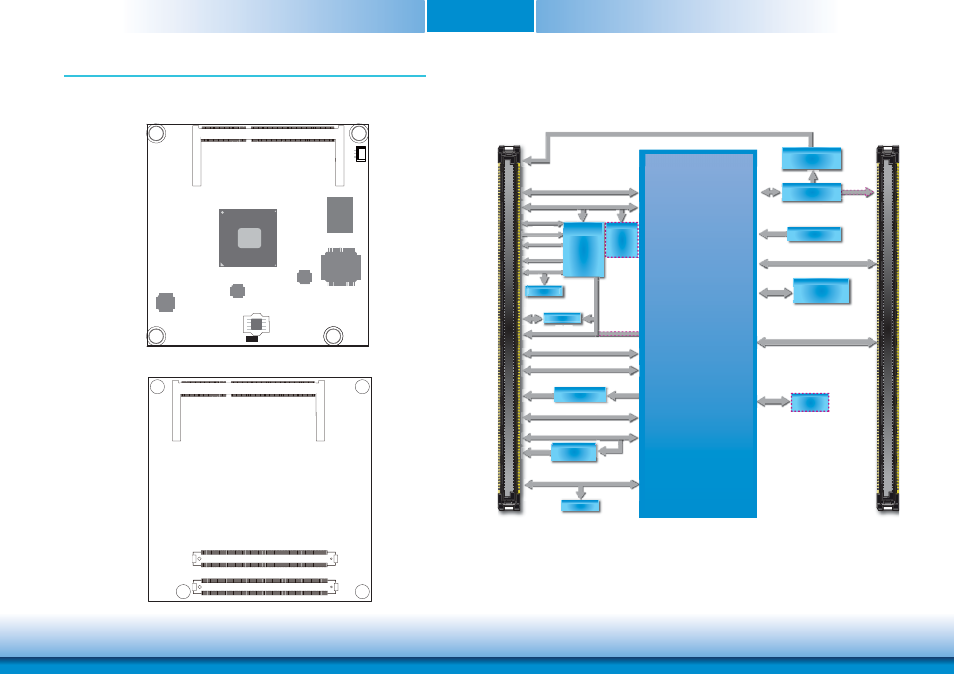
Block Diagram
DDI Port1
(to BTB DDI Port 2)
(co-lay with PTN3460)
EEPROM
USB 2.0 4x
SATA 2.0 2x
USB 3.0 Port 1
A / B
SATA 2.0 2x
SMBus
Atom E3800 Series
/Celeron
USB 3.0 Port 1
eMMC
(Optional)
eMMC
Intel
®
GLAN
I210AT
PCIe GEN2 (3 x1 or 1 x4)
LAN
SPI Flash
SPI Bus
11
)
)
C / D
LVDS Ports (Dual Channel)
DDI Port 0 (to BTB DDI Port1)
DDR3L Memory
Slot 2x
DDR3
1066/1333MHz
Dual Channel
PCIe x1
VGA
VGA
PCIe x
PCIe GEN2 (3 x1 or 1 x4)
USB4604
USB 2.0 4x
USB HSIC
HD Audio
LPC Bus
HD Audio
LPC Bus
8-bit DIO
WDT
I
2
C Bus
TPM 1.2
SLB9635
(optional)
Serial Port 0,1
Fan PWM/
TACH_IN
IMVP7
SLP/LID
WDT
SLP/LID
TCA6408A
USB 2.0 4x
DDI
Port 1
(t BTB D
1:2 DP S/W
PI3VDP612A
Default eDP (DDI) Port
eDP to LVDS
(PTN3460)
(
Embedded
Controller
IT8518E
SLP/LID
EEPROM
EEPROM
SMBus
-bit DIO
8-
SMBus
DIO
TCA6408A
C 6 08
DDR3L_1 SODIMM
Intel
BGA 1170
ITE
IT8528E
1
CPU Fan
SPI Flash BIOS
Intel I210AT
NXP PTN3460
eMMC
(optional)
SMSC USB4604
Standby Power LED
DDR3L_2 SODIMM
COM Express connector
C1
D1
C110
D110
B1
B110
A1
A110
COM Express connector