Standby power led, Cooling option, Chapter 3 standby power led – DFI BT968 User Manual
Page 25
Advertising
www.dfi .com
Chapter 3 Hardware Installation
25
Chapter 3
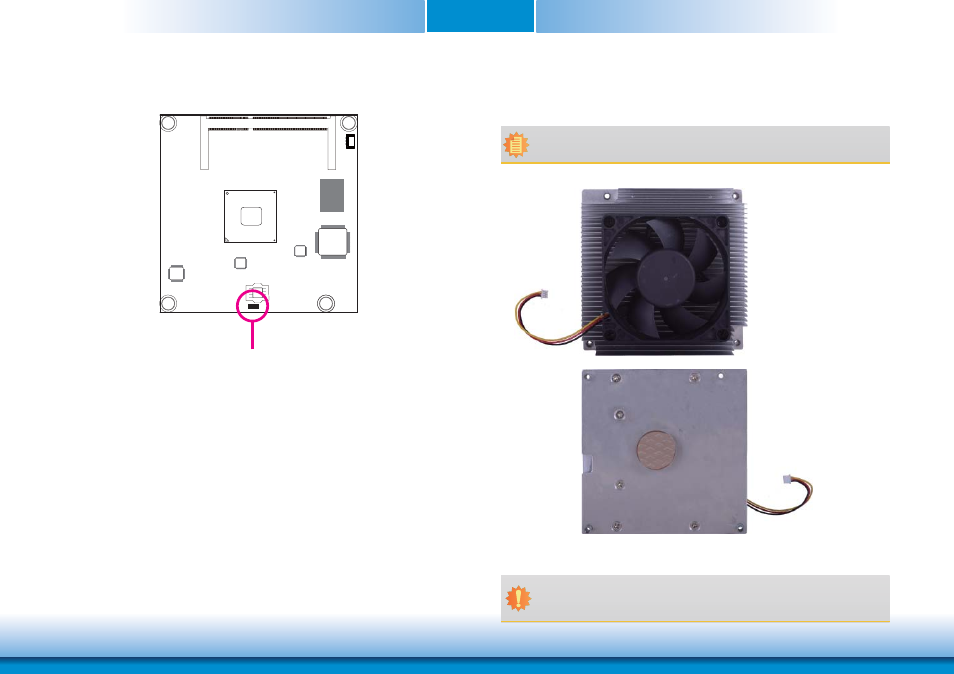
Standby Power LED
This LED will light when the system is in the standby mode.
Cooling Option
Heat Sink with Cooling Fan
• “1” denotes the location of the thermal pad designed to contact the corresponding
components that are on BT968.
Top View of the Heat Sink
Important:
Remove the plastic covering from the thermal pad prior to mounting the heat sink
onto BT968.
Note:
The system board used in the following illustrations may not resemble the actual
board. These illustrations are for reference only.
Standby
Power LED
Bottom View of the Heat Sink
1
Advertising
This manual is related to the following products: