Chapter 3 – DFI BT968 User Manual
Page 31
Advertising
www.dfi .com
Chapter 3 Hardware Installation
31
Chapter 3
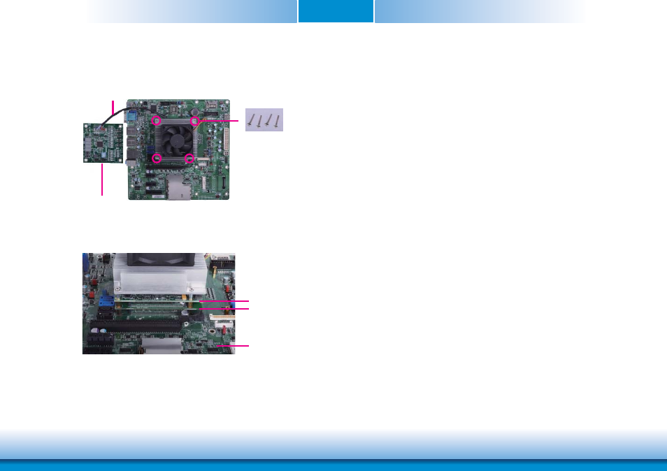
Side View of the Module, Debug Card and Carrier Board
7. Use the long mounting screws to secure the heat sink on the top of the BT968 and the
COMe-LINK1 debug card and connect the cooling fan’s cable to the fan connector on
BT968. The photo below shows the locations of long mounting screws.
COMe-LINK1
Carrier Board
BT968
Long screws
COMe-DEBUG
Cable
Advertising
This manual is related to the following products: