System memory – DFI BT968 User Manual
Page 12
www.dfi .com
Chapter 3 Hardware Installation
12
Chapter 3
System Memory
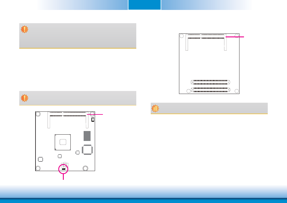
Standby
Power LED
The system board is equipped with one or two 204-pin SODIMM sockets that support DDR3L
memory modules depending on the CPU processor supported.
• Two 204-pin DDR3L SODIMM sockets (-E45/-E27/-E26/-J00/-N30)
- up to 8GB system memory
- dual channel memory interface
One 204-pin DDR3L SODIMM socket (-E25/-E15/-N07)
- up to 4GB system memory
- single channel memory interface
Important:
Electrostatic discharge (ESD) can damage your board, processor, disk drives, add-in
boards, and other components. Perform installation procedures at an ESD workstation
only. If such a station is not available, you can provide some ESD protection by wear-
ing an antistatic wrist strap and attaching it to a metal part of the system chassis. If
a wrist strap is unavailable, establish and maintain contact with the system chassis
throughout any procedures requiring ESD protection.
Important:
When the Standby Power LED lights red, it indicates that there is power on the board.
Power-off the PC then unplug the power cord prior to installing any devices. Failure to
do so will cause severe damage to the board and components.
DDR3L_1
DDR3L_2
Top View
Bottom View
Note:
When installing one DDR3L SODIMM only, make sure to install it on the socket (SO-
DIMM 1) that is located on the top side of the module.