Chapter 3 - hardware installation, Board layout, Block diagram – DFI CR902-B User Manual
Page 10: A / b c / d, Processor, Mobile intel
www.dfi .com
Chapter 3 Hardware Installation
10
Chapter 3
Chapter 3 - Hardware Installation
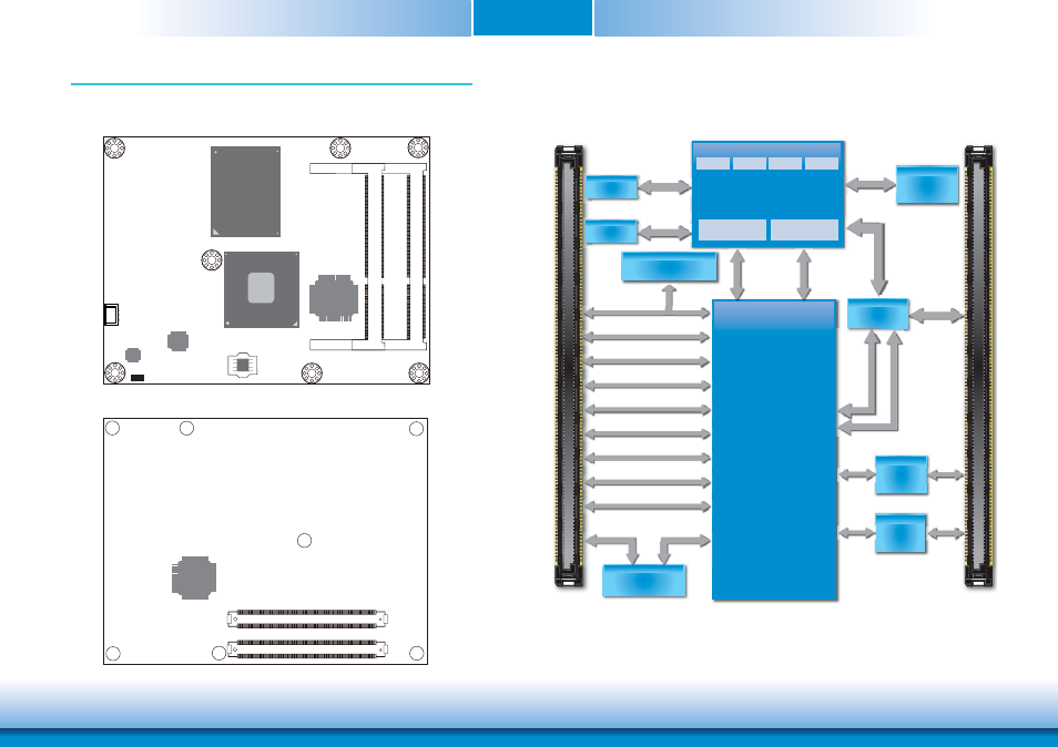
Board Layout
Top View
Bottom View
Standby Power LED
Intel 82579LM
DDR3_2
SODIMM
DDR3_1
SODIMM
1
CPU fan
Intel
CR902-B:QM77
CR902-BL:HM76
iTE
IT8518E
SPI Flash
BIOS
JMB368
Intel
BGA 1023
i3/i5/i7
COM Express connector
B1
C1
D1
B110
C110
D110
A1
A110
COM Express connector
iTE
IT8892
Block Diagram
Port B: SDVO/
HDMI/DVI
PCI Bus
IMVP7
(Vcore,Vgfx)
PEG 16x LANES
PCIe x1 5x
CRT
USB 2.0 8x
SATA 2.0 2x, SATA 3.0 2x
LVDS (Dual Channel)
Channel A
1066/1333/1600
MHz
Channel B
1066/1333/1600
MHz
0
0
3rd/2nd Generation
Intel
®
Core
™
i7/i5/i3
CORE
Processor
CORE CORE CORE
Graphics
CORE
Memory
Controller
DMI x4
(Direct Media
Interface)
Intel
®
FDI
(Flexible Display
Interface)
DDR3
SODIMM
Mobile Intel
®
QM77
(CR902-B)
Mobile Intel
®
HM76
(CR902-BL)
SM Bus
HD Audio
LPC Bus
Intel
®
GLAN
PHY 82579LM
LAN Ports
A / B
C / D
1
DDR3
SODIMM
MHz
HD Audio
LPC Bus
USB 2.0 8x
SATA 2.0 2x, SATA 3.0 2x
LVDS (Dual Channel)
CRT
PCIe x1 5x
LAN Ports
PCIe x1, Lane 8
SM Bus
Multiplexer
Switch
PEG/SDVO/
HDMI/DP Mux
PCIe x1
Lane 7
Port C: HDMI/DVI/DP
PCIe to
PCI
IDE Bus
PCIe x1
Lane 6
PCIe to
PATA
a e 6
2nd SPI Bus
2nd SPI Bus
Por
t
C:
HDMI
/DVI
/DP
Port
B: SDVO
/
HDMI
/DVI
Pt
C
HDMI
/DVI
/DP
CMOS
Backup EEPROM
P
DI
isplay
ce)