Chapter 3 – DFI CR902-B User Manual
Page 29
Advertising
www.dfi .com
Chapter 3 Hardware Installation
29
Chapter 3
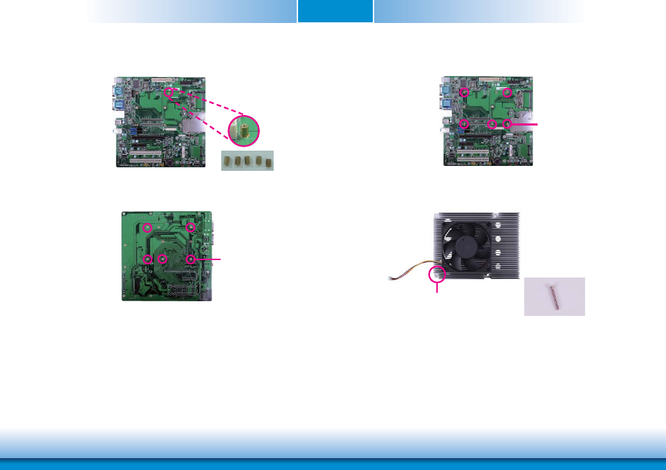
4. While supporting the mounting screw at the bottom, from the top side of the board, fasten
a bolt into the screw.
5. The photo below shows the solder side of the board with the screws already fixed in place.
Bolts
Mounting screw
6. The photo below shows the component side of the board with the bolts already fixed in
place.
7. Position the heat sink on top of CR902-B/BL series with the heat sink’s mounting holes
aligned with CR902-B/BL’s mounting holes. Insert one of the provided long screws into the
mounting hole shown in the photo below.
Bolts
Long screw
Mounting hole
Advertising
This manual is related to the following products: