Chapter 3 - hardware installation, Board layout, Block diagram – DFI HM920-HM86 User Manual
Page 10: A / b c / d, Processor, Mobile intel, Qm87 express chipset
www.dfi .com
Chapter 3 Hardware Installation
10
Chapter 3
Chapter 3 - Hardware Installation
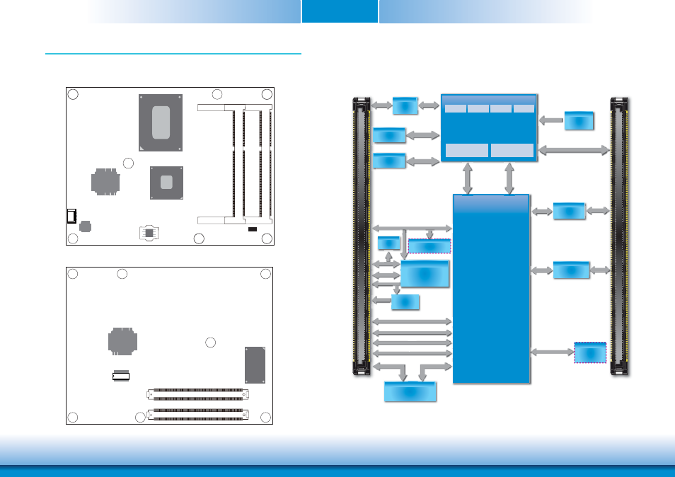
Board Layout
Top View
Bottom View
Standby Power LED
iTE
IT8892E
Intel
I217LM
DDR3L_2
SODIMM
DDR3L_1
SODIMM
SPI Flash BIOS
1
CPU fan
CPU fan
Standby Power LED
Intel
QM87/HM86
HM920-QM87: QM87
HM920-HM86: HM86
BGA 1364
Intel
iTE
IT8518E
TPM (optional)
COM Express connector
C110
D110
C1
D1
B110
B1
A110
A1
COM Express connector
SSD
(optional)
Block Diagram
For HM920-QM87
SSD Chip
(
option
)
VR12.5
(Vcore)
PEG 16x LANES
LPC TPM 1.2
SLB9635(option)
Embedded
Controller
PCIe x1, Lane 1~6
CRT
USB 2.0 8x
SATA Port
Channel A
1333/1600MHz
Channel B
1333/1600MHz
PTN
3460
LVDS Port
eDP
IT8892E
PCIe to PCI
PCIe x1
LANE7
PCI BUS
88SA8052
SATA to PATA
IDE BUS
CMOS
backup
SATA 3.0 4x
SATA
Port
4 in/4 out
DIO
t
SM Bus
DIO
LV
4 i
CORE
Processor
CORE CORE CORE
Graphics
CORE
Memory
Controller
DMI x4
(Direct Media
Interface)
Intel
®
FDI
(Flexible Display
Interface)
DDR3L
SODIMM
/
Mobile Intel
®
QM87
Express Chipset
LPC Bus
Intel
®
GLAN
PHY I217LM
LAN Port
S
A / B
C / D
DDR3L
SODIMM
/
PEG 16x LANES
LPC Bus
SM Bus
WDT
I
2
C
Bus
USB 2.0 8x
SATA 3 0 4
PCI
1 L
1 6
CRT
PCIe x1, Lane 1~6
CRT
SATA 3.0 4x
LAN Port
SATA Port
4th
Generation;
Intel
®
Core
™
i7/i5/i3
PCIe x1, Lane 8
WDT
SM Bus
WDT
n/4 outt
4 i