Chapter 3 – DFI HM920-HM86 User Manual
Page 31
Advertising
www.dfi .com
Chapter 3 Hardware Installation
31
Chapter 3
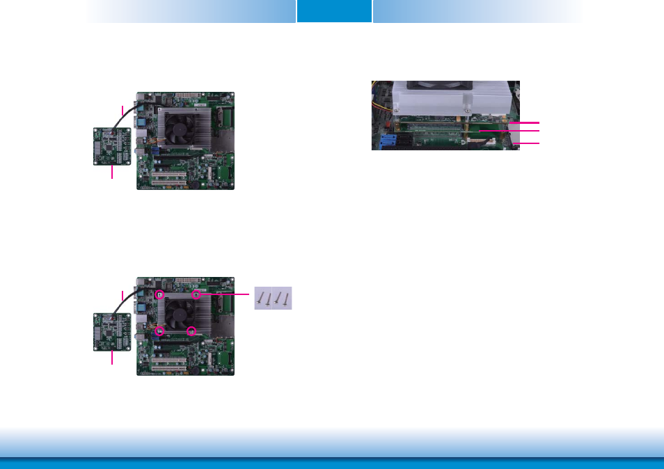
Side View of the Module, Debug Card and Carrier Board
7. Use the long mounting screws to secure them on the top of the COMe-LINK1 debug card
and the carrier board. The photo below shows the locations of long mounting screws.
6. Grasp HM920-QM87/HM86 with the heat sink by its edges and position them down firmly
on the top of the COMe-LINK1 debug card.
COMe-DEBUG
Cable
COMe-DEBUG
Cable
Long screws
COMe-LINK1
Carrier Board
COM Express Module
Advertising
This manual is related to the following products: