Field wiring, signal termination and conditioning – Measurement Computing PCI-DAS6013 User Manual
Page 15
Advertising
PCI-DAS6013 and PCI-DAS6014 User's Guide
Installing the PCI-DAS6013 and PCI-DAS6014
15
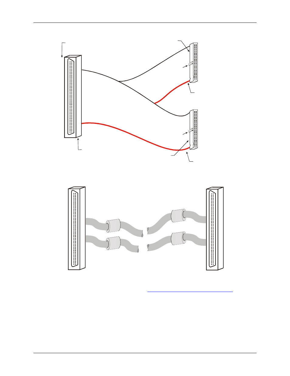
1
50
2
49
51
100
52
99
100
50
51
1
Strain relief is
stamped ―Pins 1-50‖.
Pins 1-50 are on the long side
of the ―D‖ connector.
Pins 51-100 are on
the short side of
the ―D‖ connector.
Key
Key
The red stripe
identifies pin # 1
The red stripe
identifies pin # 51
Strain relief is
Stamped ―Pins 51-100‖.
Figure 1. C100HD50-x cable
100
50
51
1
100
50
51
1
Figure 2. C100MMS-x cable
Details on these cables are available on our web sit
Advertising
This manual is related to the following products: