Digital input / output, Interrupts – Measurement Computing PCI-DAS6013 User Manual
Page 35
PCI-DAS6013 and PCI-DAS6014 User's Guide
Specifications
35
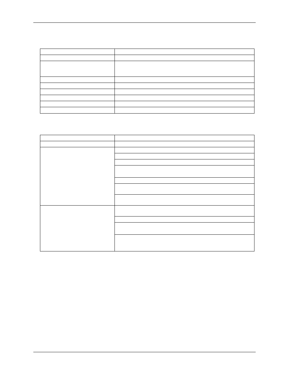
Digital input / output
Digital type
Discrete, 5V/TTL compatible
Number of I/O
8
Configuration
8 bits, independently programmable for input or output. All pins pulled up to
+5 V via 47 K resistors (default). Positions available for pull down to ground.
Hardware selectable via solder gap.
Input high voltage
2.0 V min, 7.0 V absolute max
Input low voltage
0.8 V max, –0.5 V absolute min
Output high voltage (IOH = -32 mA)
3.80 V min, 4.20 V typ
Output low voltage (IOL = 32 mA)
0.55 V max, 0.22 V typ
Data transfer
Programmed I/O
Power-up / reset state
Input mode (high impedance)
Interrupts
Interrupts
PCI INTA# - mapped to IRQn via PCI BIOS at boot-time
Interrupt enable
Programmable through PLX9080
ADC interrupt sources
(software programmable)
DAQ_ACTIVE: Interrupt is generated when a DAQ sequence is active.
DAQ_STOP:
Interrupt is generated when A/D Stop Trigger In is detected.
DAQ_DONE:
Interrupt is generated when a DAQ sequence completes.
DAQ_FIFO_1/4_FULL:
Interrupt is generated when ADC FIFO is ¼ full.
DAQ_SINGLE: Interrupt is generated after each conversion completes.
DAQ_EOSCAN: Interrupt is generated after the last channel is converted in
multi-channel scans.
DAQ_EOSEQ: Interrupt is generated after each interval delay during multi-
channel scans.
DAC interrupt sources
(PCI-DAS6014 only, software
programmable)
DAC_ACTIVE: Interrupt is generated when DAC waveform circuitry is
active.
DAC_DONE:
Interrupt is generated when a DAC sequence completes.
DAC_FIFO_1/4_EMPTY:
Interrupt is generated DAC FIFO is ¼ empty.
DAC_HIGH_CHANNEL:
Interrupt is generated when the DAC high channel output is
updated.