A/d convert signal, A/d pacer gate signal, A/d external timebase signal – Measurement Computing PCI-DAS6013 User Manual
Page 23
PCI-DAS6013 and PCI-DAS6014 User's Guide
Functional Details
23
A/D CONVERT signal
The A/D CONVERT signal indicates the start of an A/D conversion. It is available through software selection
as an input to any of the AUXIN pins (defaulting to AUXIN0) and as an output to any of the AUXOUT pins.
When used as an input, the polarity is software selectable. The A/D CONVERT signal starts an acquisition on
the selected edge. The convert pulses must be separated by a minimum of 5 µs to remain within the 200 kS/s
conversion rate specification.
Refer back to Figure 5 on page 20 and Figure 8 on page 21 for the relationship of A/D CONVERT to the DAQ
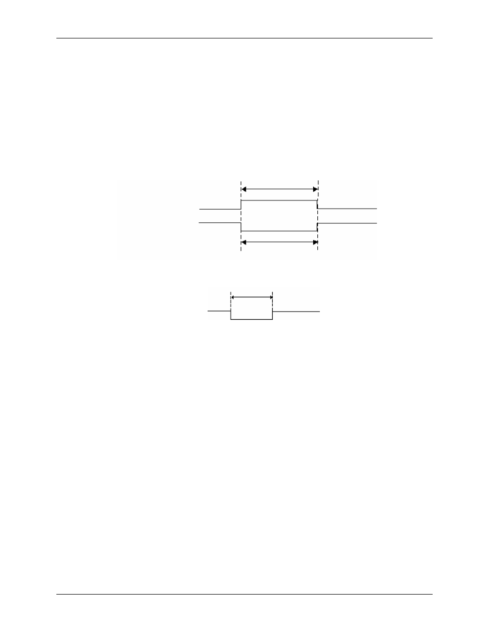
sequence. Figure 13 and Figure 14 show the input and output pulse width requirements for the A/D CONVERT
signal.
Rising Edge Polarity
t
w
t
w
= 37.5 ns minimum
Falling Edge Polarity
Figure 13. A/D CONVERT signal input timing requirement
t
w
= 50 ns
t
w
Figure 14. A/D CONVERT signal output timing requirement
The A/D CONVERT signal is generated by the on-board pacer circuit unless the external clock option is in use.
This signal may be gated by hardware (A/D PACER GATE) or software.
A/D PACER GATE signal
The A/D PACER GATE signal is used to disable scans temporarily. This signal may be programmed for input
at any of the AUXIN pins.
If the A/D PACER GATE signal is active, no scans can occur. If the A/D PACER GATE signal becomes active
during a scan in progress, the current scan is completed and scans are then held off until the gate is de-asserted.
A/D EXTERNAL TIMEBASE signal
You can use the A/D EXTERNAL TIMEBASE signal as the source for the on-board pacer circuit rather than
the 40 MHz internal time base. Any AUXIN pin can be set programmatically as the source for this signal. The
polarity is programmable.
The maximum frequency for the A/D EXTERNALTIMEBASE signal is 20 MHz. The minimum pulse width is
23 ns high or low. There is no minimum frequency specification.
Figure 15 shows the timing specifications for the A/D EXTERNAL TIMEBASE signal.