D/a convert signal – Measurement Computing PCI-DAS6013 User Manual
Page 25
PCI-DAS6013 and PCI-DAS6014 User's Guide
Functional Details
25
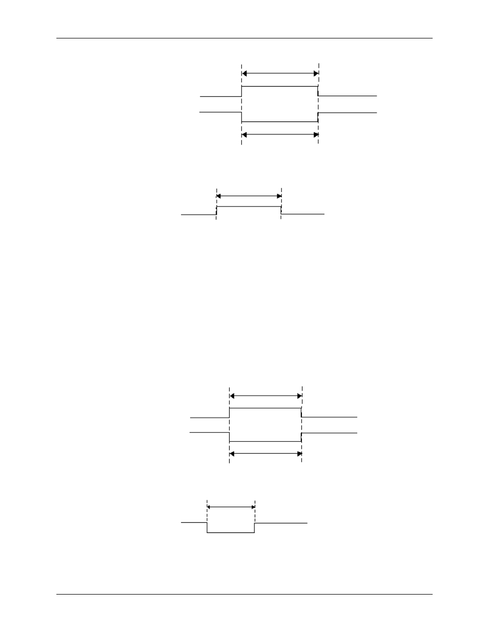
Rising Edge Polarity
t
w
t
w
= 37.5 ns minimum
Falling Edge Polarity
Figure 17. D/A START TRIGGER input signal timing
t
w
t
w
= 50 ns
Figure 18. D/A START TRIGGER output signal timing
D/A CONVERT signal
The D/A CONVERT signal causes a single output update on the D/A converters. You can program any AUXIN
pin to accept the D/A CONVERT signal. It is also available as an output on any AUXOUT pin.
The D/A CONVERT input signal polarity is software selectable. DAC outputs update within 100ns of the
selected edge. The D/A CONVERT pulses should be no less than 100 µs apart.
When used as an output, the D/A CONVERT signal may be used to monitor the pacing of the output updates.
The output has a pulse width of 225 ns with selectable polarity.
The following figures show the input and output timing requirements for the D/A CONVERT signal.
Rising Edge Polarity
t
w
t
w
= 37.5 ns minimum
Falling Edge Polarity
Figure 19. D/A CONVERT input signal timing
t
w
t
w
= 225 ns
Figure 20. D/A CONVERT output signal timing