Online power, 2 rev a – OnLine Power Telecommunication User Manual
Page 17
OnLine Power
1-2
REV A
INPUT AC ON
RED
GREEN
OVER LOAD
INVERTER ON
100%
25%
SUMMARY ALARM
HIGH BATTERY CAPACITY
LOW BATTERY
BYPASS ON
MEDIUM BATTERY CAPACITY
ON BATTERY
UPS ON S2
UPS OFF S1
SWITCH
LOAD IN
PERCENTAGE
OF RATED AMPS
ELECTRONIC TRAY - STATUS PANEL
ILLUSTRATION 1-1
In the normal running condition, “Input AC ON” (Green LED) and “Bypass ON” (Green LED) is lit ON indicating that
input AC power is available and unit is running in AC mode (Off-Line), in Bypass mode. When input power is lost or
disappears, “Input AC ON” green LED shuts OFF, “Bypass ON” green LED shuts OFF. “ON Battery” and “Inverter
ON” green LEDs lit ON indicating that output power is supplied from battery & inverter (unit is running on battery and
inverter).
1-2-1 Alarm
Signals
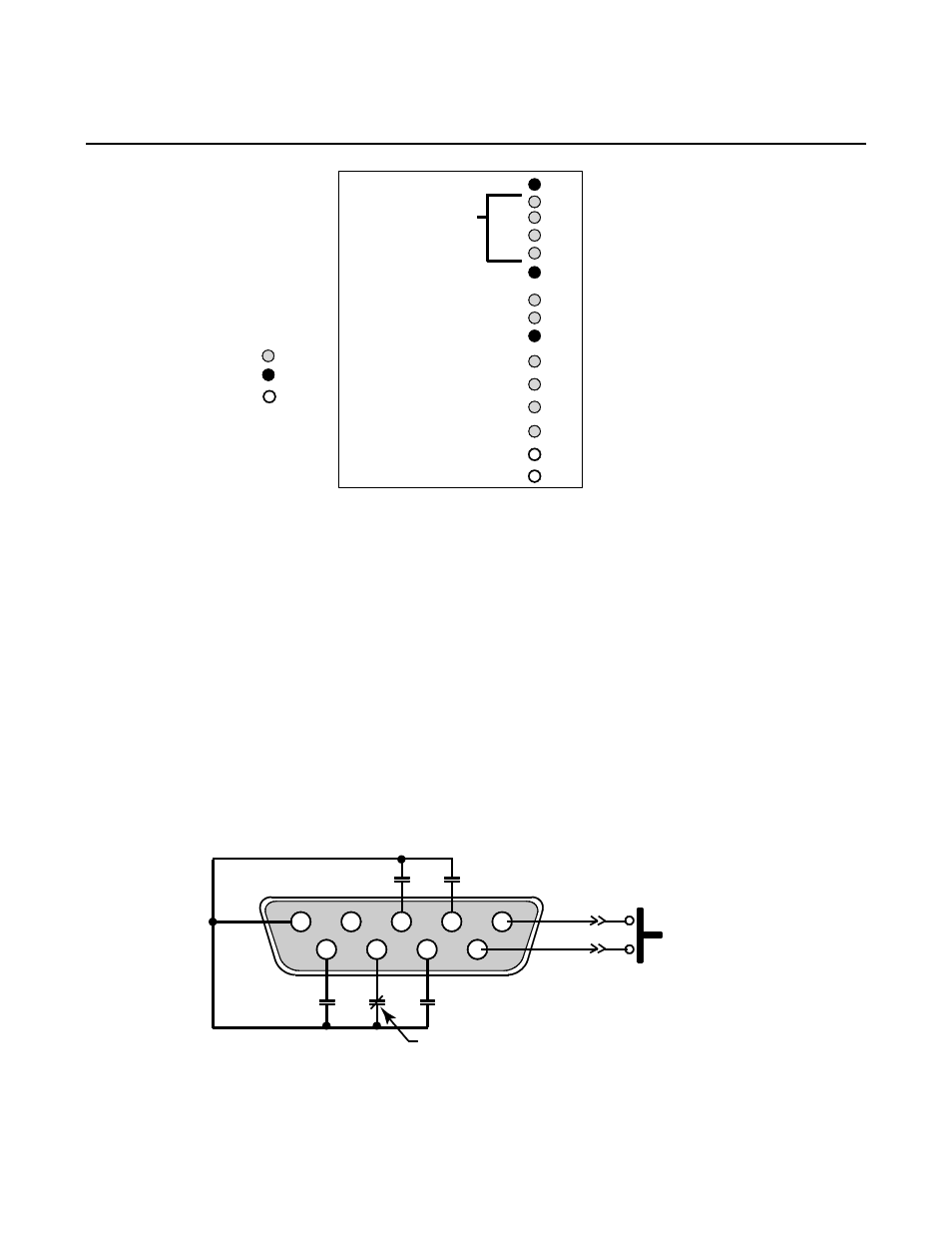
Also providing information on the unit’s status/particular aspects to the outside world by way of electrical signals is a
DB-9 connector. This DB-9 connector is located on the front console of the Electronic Tray. This interface provides
a set of open and closed contacts, which relate the status of PBC-II to the outside world. An interface DB-9
connector and cable permit the unit to bring out following signals with their normal state (open or closed). The
contacts (Normally Open or Normally Closed) is shown when unit is running in normal condition (i.e. with input
power present and everything normal within limit).
1
2
3
4
5
9
8
Input AC ON
Summary Alarm
UPS ON (Normally Close)
Low Battery
ON Battery
7
6
Door Switch
(Normally Open)
(Normally Open)
(Normally Open)
(Normally Open)
(Normally Open)
NOTE: Relays are dry contacts
rated 2 AMPS @ 250 VAC
DB9 CONTACTS
ILLUSTRATION 1-2